Ultralow-EMI, 96W, Step-Down μModule Regulator—EN55022 Class B Certified in a 15mm x 15mm Footprint
Ultralow-EMI, 96W, Step-Down μModule Regulator—EN55022 Class B Certified in a 15mm x 15mm Footprint
Jan 1 2012
Designers of information technology and communications systems have come face-to-face with the difficult challenge of producing feature-rich, power-hungry products that comply with international EMI standards. Prior to sale, all information technology equipment (ITE)—commonly defined as having a regulated clock signal greater than 9kHz—must meet government standards such as FCC Part 15 Subpart B in the United States, and EN55022 in the European Union. Both standards define maximum allowable radiated emission for industrial and commercial environments (Class A) and home environments (Class B) as shown in Figure 1.
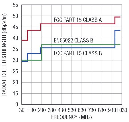
Figure 1. FCC radiated limits (USA) and EN55022 class B radiated limit (European Union).
The problem is that the power budgets of ITE products are increasing with performance improvements, so meeting EMI standards becomes proportionally more difficult (see sidebar). Enter the LTM4613 8A μModule® step-down regulator, which saves significant design time by squeezing guaranteed EMI-compliance and high performance into a single compact package.
Electromagnetic Theory and EMI Switch Mode Regulators
A short reflection on electromagnetic theory can help one understand the EMI implications of high current, high power DC/DC step-down converters.
Gauss’ law states that the strength of an electric field in a given area over an enclosed volume is proportional to the total charge inside it.

Consider this law as applied to a circuit board. A PCB trace is simply a volume of charge, where the amount of charge in it is proportional to the amount of current passing through it (specifically, one ampere equals one coulomb of charge per second.) So, higher currents create stronger electric fields.
Additionally, in a switch mode regulator, these fields vary in strength as currents change throughout the switching cycle. Maxwell’s equations tell us that a constantly varying electric field creates a self-sustaining electromagnetic wave.
If currents change rapidly, as is the case in a switch mode regulator, some of the electromagnetic energy is radiated into the environment, which can cause electromagnetic interference (EMI). EMI is produced by all of the current loops within a step-down regulator. In general, EMI mitigation becomes increasingly important, and difficult, as power consumption goes up.
While this short description is incomplete, leaving out, for example, the implications of the magnetic component surrounding the current paths and the rapid polarity changes on the inductor, it shows the relationship between a regulator’s increasing output power and radiated EMI, which must be addressed with good design practices.
EMI Radiation Sources
Electromagnetic waves radiate from any switching converter and its interface leads. Pulsating voltages and currents associated with the switching action of all switch mode converters from ideal sources generate and directly influence the strength of radiated electromagnetic waves. Furthermore, parasitic devices within the converter contribute to electromagnetic radiation. Figure 2 presents a typical buck converter including parasitic inductors and parasitic capacitors of the MOSFETs.
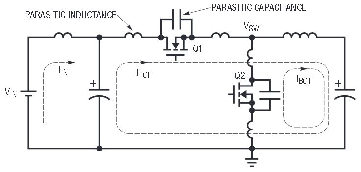
Figure 2. Buck switching regulator with parasitic inductor and capacitors.
During MOSFET switching, the energy stored in the parasitic inductor resonates with the energy stored in the parasitic capacitor. When the energy is released, the resulting voltage spike at the switch node (VSW) can be as large as twice of the input voltage, as shown in Figure 3. As the current capability of the MOSFET increases, the energy stored in the parasitic capacitor tends to increase as well. The switching action also pulses the input current and the current flowing through both top MOSFET (ITOP) and bottom MOSFET (IBOT). This pulsating current generates electrical waves on the input supply cable and on the PCB board traces, which act as transmitting antennae.
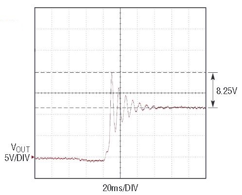
Figure 3. Typical switch node voltage spike and ringing in a 12V input buck switching regulator.
The magnitude of the voltage spike at the switching node increases as input voltages and output currents increase. Likewise, the higher the output current, the larger the pulsating current generated inside the circuit loop. In the end, radiated emission is highly dependent on the operating condition of the device, so testing should take into account worst-case conditions. In general, radiated EMI increases with higher input voltage and higher output power, particularly output current.
Linear regulators are the usual go-to, low-EMI alternative to switching regulators, but power levels and input voltages have reached a point where linear regulators produce too much heat to be practical. Design engineers are thus forced to overcome the EMI challenges of switching regulators in order to meet the performance requirements of today’s equipment.
EMI Mitigation
There are several ways to reduce the radiated emissions from a switch mode power converter design. One conventional method is to surround the entire power solution with an EMI shield, essentially containing the EMI field within a metal enclosure. The obvious problem is that a metal box adds significant complexity, size and cost. Alternatively, an RC snubber circuit at the switching node (VSW) can reduce the voltage spike and subsequent ringing, but adding an RC snubber circuit significantly reduces operating efficiency. Finally, careful PCB layout, such as using local low ESR ceramic decoupling capacitors and minimizing PCB trace distances for high current paths, can reduce the parasitic inductance as shown in Figure 2 and help reduce EMI.
Overall, a power engineer must apply years of experience to evaluate tough trade-offs when designing a power supply that meets stringent size, efficiency, heat and EMI specifications, especially in high input voltage, high output power applications. Often, a huge amount of time and energy are spent evaluating the trade-offs inherent in designing an EMI-compliant power converter.
Ideally, extensive design experience and best practices could be prepackaged into a converter that complies with EMI standards while minimizing performance trade-offs. Fortunately, that ideal is achieved by the LTM4613.
Guaranteed EMI Compliance
The LTM4613 8A μModule step-down regulator is certified by an independent test laboratory, TUV Rheinland, to meet EN55022 Class B EMI emissions limits at up to 96W of output power (Figure 4). TUV Rheinland is ISO 17025 accredited by the U.S. National Institute of Standards and Technology (NIST) in North America and the Notified Bodies on the European Union, the most meticulous and recognized certifying labs in the industry. Figure 5 shows a complete radiated emissions 30MHz to 1000MHz test setup using the standard LTM4613 demonstration board (DC1743) in TUV Rheinland’s 10-meter semi-anechoic chamber as specified by EN55022.
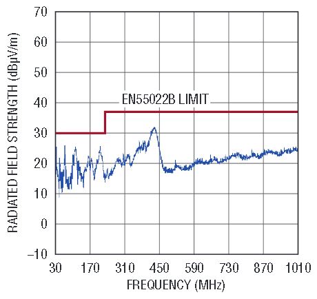
Figure 4. Demonstrated EN55022 compliance LTM4613 (DC1743) at 96W as conducted by independent tests.
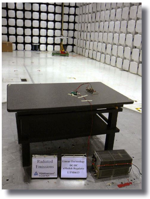
Figure 5. Radiated emission test setup.
EMI compliance is worthless if the regulator can’t meet other stringent space and performance requirements. That’s where the LTM4613 excels. This nearly complete converter comes in a space-saving 15mm × 15mm package that requires only input capacitance, output capacitance, and a few other small components to make a step-down regulator. Performance is optimized to minimize power dissipation, maximize efficiency and assure tight regulation. The LTM4613 accepts input voltages from 5V to 36V and delivers a regulated output voltage from 3.3V to 15V with 2.0% maximum total DC error over line, load and temperature. A 24V input to 12V output conversion reaches peak operating efficiencies of around 95%.
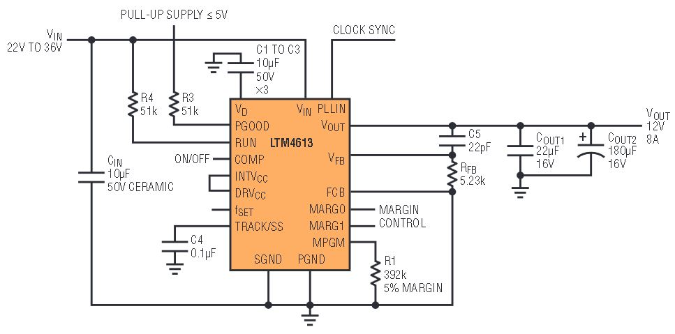
Figure 6. LTM4613 12V/8A output application circuit.
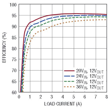
Figure 7. LTM4613 efficiency vs load current with 12V output.
Conclusion
The LTM4613 delivers high output power and efficiency with demonstrated EMI performance that complies with EN55022 Class B. With carefully designed integrated filter, meticulous internal layout, shielded inductor, internal snubber circuitry and power transistor driver, the LTM4613 achieves a perfect balance between the size, output power, efficiency and emission. The LTM4613 eliminates the need for external filters, magnetic shields, and ferrite beads for a trouble-free design process, making it easy to design safe, EMI-compliant power supplies.
When comparing products, be certain the EN55022 certification was performed under similar conditions, as EMI field strength and the ability to pass EMI regulations is highly dependent on factors such as the input voltage, output current, output voltage and PCB layout. All LTM4613 test operating conditions and design files are freely available. Designers using the LTM4613 can be confident that it will perform as certified.


