Ultra-Low Cost +30dBm PA for GSM and 900MHz-ISM Applications
Abstract
This application note, based on the MAX2235 power amplifier (PA) shows the operation in GSM and 900MHz ISM band applications. +30dBm of output power is achieved with 40 percent efficiency. The device provides 24dB gain, and operates with a 2.7V to 5.5V power supply. A schematic, the circuit board layout, and a bill of material are provided.
The MAX2235 is a low-cost, non-linear power amplifier, intended for constant-envelope applications. Originally characterized for US AMPS, this application note demonstrates the use of the device for European GSM, 868MHz European-ISM and US 900MHz-ISM band applications.
At 900MHz, the device delivers over +30dBm of output power at 40% efficiency, with 24dB of gain from a +5V supply. The device can be operated from a single +2.7V to +5.5V voltage supply. A gain-control pin allows the output power to be varied over a 35dB range. A low-power shutdown mode reduces supply current consumption to less than 1µA. A key feature of this PA is output power autoramping, which minimizes transient noise and spectral splatter.
Figure 1 demonstrates the output power performance of the MAX2235 over the 880MHz to 915MHz frequency band. Figures 2 through 4, demonstrate the output power, efficiency and supply current performance of the MAX2235 versus input power and frequency. Figure 5 demonstrates the output power of the MAX2235 versus gain control voltage.
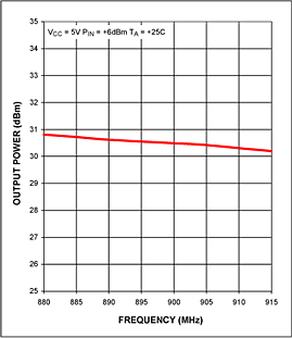
Figure 1. The MAX2235 output power vs frequency.
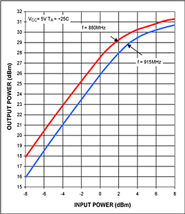
Figure 2. The MAX2235 output power vs input power.
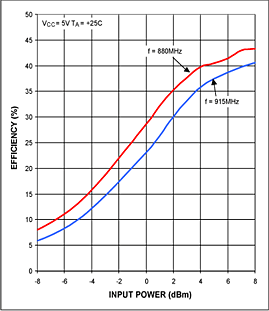
Figure 3. The MAX2235 efficiency vs input power.
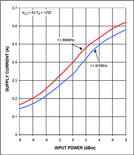
Figure 4. The MAX2235 supply current vs input power.
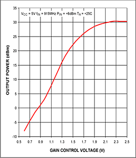
Figure 5. The MAX2235 output power vs GC voltage.
Figures 6 and 7 demonstrate the component changes and placement required to tune the MAX2235 for operation over the 880MHz to 915MHz frequency band.
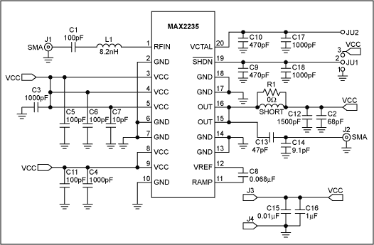
Figure 6. Schematic for the MAX2235 PA for GSM and 900MHz.
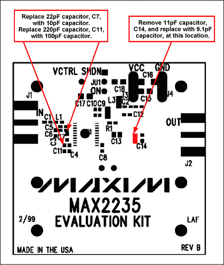
Figure 7. Component Placement Guide for the MAX2235 PA for GSM and 900MHz.
Table 1 lists the component values.
| Designation | Qty | Description |
| C1 | 1 | 100pF, 5% ceramic capacitor (0603) Murata GRM39COG101J050V |
| C2 | 1 | 68pF, 5% ceramic capacitor (0603) Murata GRM39COG680J050V |
| C3, C4 | 2 | 1000pF, 10% ceramic capacitors (0603) Murata GRM39X7R102K050V |
| C5, C6 | 2 | 100pF, 5% ceramic capacitors (0402) Murata GRM36COG101J050V |
| C7 | 1 | 10pF, 5% ceramic capacitor (0603) Murata GRM39COG100J050V |
| C8 | 1 | 0.068µF, 10% Murata GRM39X7R683K016V |
| C9, C10 | 2 | 470pF, 10% ceramic capacitors (0603) Murata GRM39X7R471K050V |
| C11 | 1 | 100pF, 5% ceramic capacitor (0603) Murata GRM39COG101J050V |
| C12 | 1 | 1500pF, 10% ceramic capacitor (0603) Murata GRM39X7R152K0504 |
| C13 | 1 | 47pF, 5% ceramic capacitor ATC 100A470JW150X |
| C14 | 1 | 9.1pF, 5% ceramic capacitor ATC 100A9R1JW150X |
| C15 | 1 | 0.01µF, 10% ceramic capacitor (0805) Murata GRM40X7R103K050V |
| C16 | 1 | 1µF, +80%, -20% ceramic capacitor (1206) Murata GRM42-6Y5V105Z025V |
| C17, C18 | 2 | 1000pF, 10% ceramic capacitors (0805) Murata GRM40X7R102K050V |
| L1 | 1 | 8.2nH (0603) inductor Toko LL1608-FH8N2K |
| L3 | 1 | 30-gauge wire short |
| J1, J2 | 2 | SMA connectors (PC edge mount) E.F. Johnson 142-0701-801 |
| J3, J4 | 2 | Test points |
| JU1 | 1 | 3-pin header (0.1" centers) |
| R1 | 1 | 0Ω resistor (0603) Kamaya RMC16-000T |
| VCTRL | 1 | 1-pin header |
| U1 | 1 | MAX2235EUP (TSSOP-20) |
| None | 1 | MAX2235 EV kit PC board |
Related to this Article
Products
Product Categories


