Abstract
If an application requires writing to EPROM devices after deployment, 5V devices need to be protected from overvoltage exposure. This article explains how to have 1-Wire EPROMs and 5V 1-Wire devices on the same bus, if the 5V devices are protected from the programming pulse.
Introduction
Most 1-Wire devices work with 2.8V to 5.25V VPUP for read and write. EPROM devices (including the DS2406, DS2502, DS1982, DS2505, and DS1985) require a 12V programming pulse for writing. The programming pulse, however, constitutes overvoltage for devices that cannot sustain more than 5.5V. Therefore, if the application requires writing to EPROM devices after deployment, 5V devices need to be protected (Figure 1). The circuit featured in this document protects from positive overvoltages up to 40V including 12V EPROM programming pulses.
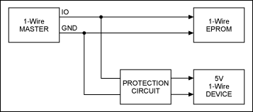
Figure 1. A 1-Wire bus with 5V and 12V devices.
Protection Circuit Requirements
A suitable protection circuit needs to meet several requirements:
- Impose a very low load on the 1-Wire bus
- Not impede programming of 1-Wire EPROMs
- Properly protect 5V 1-Wire devices
- Maintain the full communication signal amplitude
In addition, it is desirable that a protection circuit be built from easily available, inexpensive components.
The Basic Concept
Figure 2 shows a very simple protection circuit. The zener diode U1 limits the voltage at the gate of Q1. R1 limits the current that can flow through U1. Q1 is an n-channel MOSFET that operates as a source follower, letting the voltage from its gate minus an offset reach the IO pin of the 1-Wire slave. To maintain the full communication signal amplitude, the offset should be as low as possible. Well suited for this purpose are depletion mode MOSFETs, which have a negative offset. The Supertex® DN3135 was tested and its offset was measured as -1.84V (data sheet parameter VGS(OFF)). Consequently, the necessary gate voltage VG is 3.16V, which defines the threshold voltage of U1.
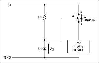
Figure 2. The concept of a protection circuit.
Unfortunately, the transistor's offset voltage varies based on device and temperature. Instead of -1.84V, the value could be anywhere between -3.5 and -1.5V at room temperature. This variation makes finding the appropriate zener diode difficult. In addition, low-voltage zener diodes are typically specified at 5mA, a current that would impede the programming of 1-Wire EPROMs. If operated at 100µA, for example, the voltage drop is far below the specified threshold. Better suited are shunt regulators, which are similar to zener diodes, but reach their threshold voltage at a much lower current. The 3.3V version of the Maxim LM4040, for example, needs just 67µA to reliably reach the reverse breakdown voltage. Defining that 67µA are reached at 5V on the 1-Wire bus, one can calculate R1 = (5V - 3.3V)/67µA = 25.4kΩ. The additional load of 67µA on the 1-Wire bus corresponds to approximately 10 slave devices. This is acceptable for a 1-Wire master like the DS2480B. Now we will check the current through R1 during a 12V programming pulse:
I(R1) = (12V - 3.3V)/25.4kΩ = 343µA
The programming current for 1-Wire EPROMs is specified as 10mA. The additional load of roughly 1/3mA should not cause any problems. Therefore, the circuit in Figure 2 should work if the MOSFET's offset voltage is close to -1.8V. This, however, is not guaranteed. Therefore, a circuit that provides an adjustable threshold or can be trimmed is needed.
Adjustable Threshold with Monolithic Current Source
The circuit in Figure 3 uses a current source (U1) to set the maximum gate voltage for Q1. An ideal current source delivers a current that is independent of the voltage across its terminals. With a given current IOUT, the gate voltage can be adjusted by choosing different values for R1.
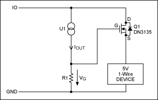
Figure 3. Concept of an improved protection circuit with current source.
A generally available monolithic current source is the NXP® PSSI2021SAY (Figure 4). The device has four terminals, called VS, IOUT, GND, and REXT. REXT, if installed, bypasses an internal resistor of nominal 48kΩ.
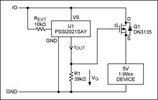
Figure 4. Improved protection circuit.
According to the product data sheet, IOUT is calculated as:
IOUT = 0.617/REXT(Ω) + 15µA
With REXT = 10kΩ, to mitigate the tolerance of the 48kΩ internal resistor in parallel to REXT, the typical current is (61.7 + 15)µA = 76.7µA, according to the PSSI2021SAY data sheet. The output current depends to some extent on the supply voltage VS, in particular for supply voltages below 5V. When measured in a test setup, the value of 76.7µA was reached at 3.75V. At 12V, the current was 94µA. This behavior should be considered normal due to the chip's simple design.
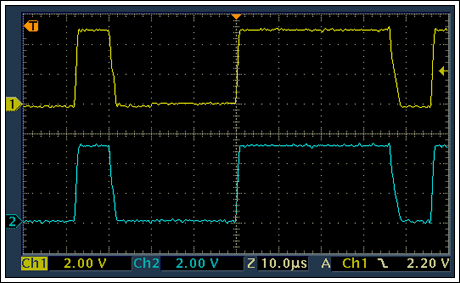
The circuit of Figure 4 was tested with REXT = 10kΩ and R1 = 39kΩ. The 1-Wire adapter was a Maxim DS9097U-E25. Figures 5 and 6 show the signals at the 1-Wire adapter (top trace) and protected slave (bottom trace). The programming pulse (see Figure 6), causes a ±3V spike of ~10µs duration at the protected slave. During the programming pulse, the voltage at the protected slave rises to 6V, which can be problematic.
f37230e3abcf43b29ad929581d528f44
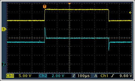
Figure 6. Programming pulse, adapter (top), protected slave (bottom).
A downside of the PSSI2021SAY is its fairly high supply current. At 12V, including 15µA for IOUT, the current could be as high as 370µA. Besides the adjustability, the circuit with PSSI2021SAY is not better than the circuit in Figure 2.
Adjustable Threshold with Bandgap Reference and Discrete Current Source
The PSSI2021SAY data sheet discloses the basic concept of the circuit. One of the weaknesses is the internal reference voltage, which is derived from the forward voltage of two diodes in series. Better performance is achieved if a bandgap reference is used instead of forward biased diodes. Figure 7 shows a circuit that is equivalent to the PSSI2021SAY and consumes less current, and the current is practically voltage independent once the bandgap reference has reached its normal operating current.
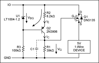
Figure 7. Protection circuit with bandgap reference.
The PSSI2021SAY is replaced by transistor Q2, bandgap reference U1, and resistors R2 and R3. With R3 chosen as 100kΩ, the bandgap reference reaches its minimum operating current at 2.2V on IO. The current through U1 is 38µA at 5V and 108µA at 12V on IO.
According to Kirchhoff's law, the following relationship applies:
VBG = IE × R2 + VEB
For a general-purpose silicon pnp transistor such as the 2N3906, VEB is typically 0.6V at room temperature and low collector current. With VBG known as 1.235V, this equation can be resolved to:
R2 = (VBG - VEB)/IE = (1.235V - 0.6V)/IE = 0.635V/IE
To achieve the same nominal current as with the PSSI2021SAY circuit (76.7µA), R2 is calculated as 8.2kΩ. With Q1 being the same as in Figure 2, VG must be 3.2V. Neglecting the Q2's base current, IC is equal to IE. R1 now can be calculated as:
R1 = VG/IC = 3.2V/76.7µA = 41.7kΩ
To lower the overall load on the 1-Wire master, one could lower the output current of the current source. Increasing both R1 and R2 by a factor of 4 (R2 = 33kΩ, R1 = 160kΩ) reduces the current to 19µA, resulting in a maximum gate voltage of 3.08V. In practice, R1 needs to be adjusted to compensate for the MOSFET's VGS(OFF) tolerance. The proper value is found if the voltage at the 1-Wire slave closely matches V(IO).
The circuit in Figure 7 was tested with a National Semiconductor® LM385 instead of the newer and improved Linear Technology® LT1004, which was not readily available. The 1-Wire adapter was a Maxim DS9097U-E25. Figures 8 and 9 show the signals at the 1-Wire adapter (top trace) and protected slave (bottom trace). The programming pulse (see Figure 9), causes a ~10µs spike (2V rising, 1.5V falling) at the slave. This circuit has a better performance than the circuit in Figure 4. During the programming pulse, the voltage at the protected slave just barely rises above the 5V level.
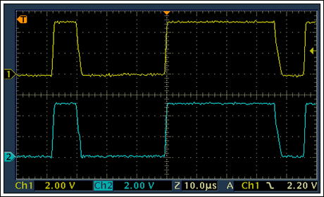
Figure 8. Without C1. Communication waveforms, adapter (top), protected slave (bottom).
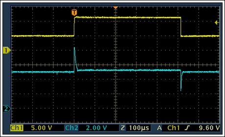
Figure 9. Without C1. Programming pulse, adapter (top), protected slave (bottom).
To lower the amplitude of the spike caused by the programming pulse, C1 with a value of 100pF was installed. Figures 10 and 11 show the result. The communication waveform is slightly distorted. The amplitude of the spike is reduced (1.4V rising, 1.2V falling). In contrast to Figure 9, the voltage does not fall below 3V. A 5.1V low-power zener diode, like the BZX84, from the source of Q1 to GND can clip the rising spike, but does not affect the falling spike.
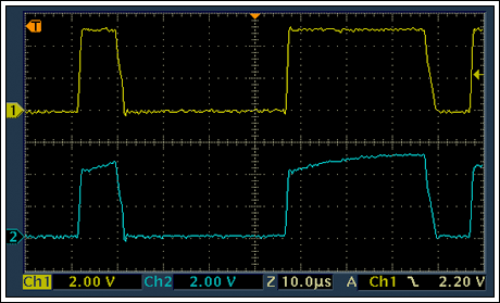
Figure 10. C1 installed. Communication waveforms, adapter (top), protected slave (bottom).
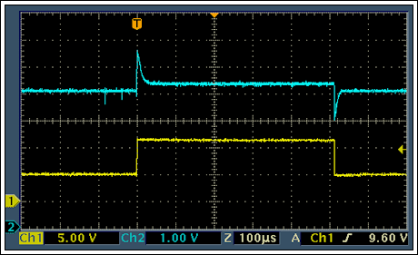
Figure 11. C1 installed. Programming pulse, adapter (bottom), protected slave (top).
Protection Limits
The maximum voltage that the circuit in Figure 7 can sustain between IO and GND is determined by:
- The maximum current that is safe for U1
- The VCE breakdown voltage of Q2
- The VGD and VDS breakdown voltages of Q1
These values are 20mA for LT1004 (U1), 40V for 2N3906 (Q2), and 350V for Q1. The limiting component is Q2. At 40V, the current through U1 is 143µA, far below the 20mA limit.
Summary
It is possible to have 1-Wire EPROMs and 5V 1-Wire devices on the same bus if the 5V devices are protected from the programming pulse. The simple protection circuit in Figure 2 works, but is not optimal due to the wide variation of the MOSFET's gate-to-source off voltage; one needs to find a "matching pair" of a transistor and shunt regulator. The circuit in Figure 4 is adjustable to compensate for the MOSFET's tolerance, but imposes a larger load on the 1-Wire master. Since the PSSI2021SAY can sustain up to 75V, this circuit can protect from voltages up to 75V. The circuit in Figure 7 is functionally equivalent to the one in Figure 4, but has a better performance and imposes a much lower load on the 1-Wire master. Its protection level is 40V, limited by Q2. The protection level can be increased by choosing a transistor with a higher VCE breakdown voltage.


