Abstract
Line and load transient measurements show a power supply's ability to respond to abrupt changes in line voltage and load current. These tests show how the controller responds to load and line steps and reveal significant overshoot, or sustained ringing in the output as it attempts to maintain regulation. Line and load response is analyzed in detail along with test circuits and an example.
Line and load transient measurements illustrate a power supply's ability to respond to abrupt changes in line voltage and load current. The test measurements can reveal significant overshoot or sustained ringing in the output as it attempts to maintain regulation. Line transient response is different from power-supply rejection ratio (PSRR). PSRR is a DC measurement, while a line transient is a step function containing the Fourier components of the step. A load transient is similar, except that it is a load current step and injects a disturbance into the power supply output. In contrast, a line transient injects the disturbance at the input.
Background (What Do Line and Load Transients Tell Us about a Power Supply?)
Line and load steps indirectly inject a stimulus into the controller at the Fourier components of the step. If the step, f(t), in line or load has infinitely fast edges, then it can be represented by the Fourier Series:

Loop Gain Attenuation
A simplified control diagram (Figure 1) for a power supply with no feedback would consist of the controller filter gain, the output impedance, and the input and output signals. Line and load steps are represented as inputs, (ILOAD(s) and VIN(s)).
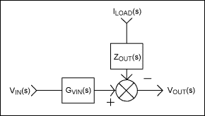
Figure 1. Simplified power-supply control diagram with no feedback.

GVIN(s), the controller's filter gain, is the small signal gain from input to output. A buck converter with no feedback, for example, has a filter gain from input to output of:

ZOUT(s) is the output impedance. In the buck converter case, the output impedance is:

Any input voltage or load current disturbance propagates through to the output and directly affects the output voltage. For example, a buck converter operating with VIN = 12V and a forced 50% duty cycle gives an output voltage of 6V. A 2V step change in the input voltage results in a 1V step change in the output voltage. Figure 2 shows a control loop with feedback added. In this example the output is made to regulate to a set reference value, VREF, and is less sensitive to input voltage and output current changes.
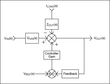
Figure 2. Simplified power control diagram with feedback.
The output voltage is now equal to:

With the addition of feedback, it can be seen that at the disturbances' output the effects from input voltage and load current variations are attenuated by the term (1 + GFB x GC(s)). The term GFB is the feedback divider gain and GC(s) is the controller gain, which contains the power filter, the error amplifier, and other gain elements in the control loop. The term GFB x GC(s) is called the loop gain. By injecting a signal into the feedback path, a Bode plot of gain and phase of GFB x GC(s) can be developed that show how much attenuation the controller has at the output due to disturbances in VIN and ILOAD. Of special concern is the crossover frequency, fC, where GFB x GC(s) = 1, and its associated phase shift. As the phase margin (the difference between 180° and the phase shift at fC) approaches 0°, there can be unwanted effects on the transient response. At frequencies above crossover, the loop gain falls below 1, and the line and load transient attenuation is the same as if the power supply had no feedback.
Time Domain to Frequency Domain
If the loop gain at crossover has only a single pole (i.e., all other poles and zeroes in the loop gain are significantly far away from crossover to have negligible affect), then the loop gain can be expressed as:

Figure 3 shows a single-pole response where the gain rolls off at -20dB/decade and crosses unity gain with a 90° phase shift.
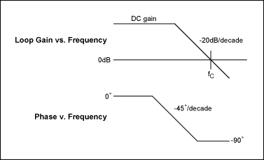
Figure 3. Bode plot of single-pole loop gain.
With the single-pole response, the loop gain decreases with frequency, as does the attenuation of the transient disturbance components. By multiplying

by the frequency domain step function, 1/s, and taking the inverse Laplace Transform, the time domain response is obtained. A load step response (ΔILOAD) into a controller with this loop gain will exhibit an exponential response in the time domain. The initial drop will be, ΔV = ILOAD(s) x ZOUT(s) and the recovery will take the form VFINAL = ΔV x (1 - e-t/τ). VFINAL is the DC value of VOUT before the load step. At one time constant, τ = 1/(2πfc the output voltage will have recovered 63% of the initial drop (ΔV).
A line step on the input side of the power supply will raise the voltage at the output by the filter gain, GVIN(s), multiplied by the input voltage step, VIN(s). Here the result is the same as for the load step: after 1 time constant, (τ = 1/2π x fc), the output voltage recovers 63% of the initial excursion.
The single-pole loop which results in a 90° phase margin is a conservative approach for the loop gain at crossover. Alternatively, the loop gain can be affected by multiple poles around crossover, resulting in a phase margin less than 90°. This causes the step response in the time domain to show overshoot, and eventually ring as the phase margin gets closer and closer to 0°. This can be understood by realizing that the magnitude of the open-loop gain at crossover is equal to 1. As the phase margin decreases below 90°, the real portion of the loop gain becomes negative. As the phase margin decreases further, the "real" portion becomes increasingly more negative than the imaginary portion. This causes the magnitude of the denominator in the closed-loop gain to become less than unity, resulting in gain at frequency components near crossover.
A two-pole open loop gain is a good example of what happens during a step response as the phase margin is decreased. For example, a loop with 60dB of DC gain is designed, showing the effect of two real poles at crossover. This can be written as:

The closed-loop gain will be

Unity-gain crossover occurs at a frequency between ω1 and ω2. Then ω1 and ω2 are adjusted to vary the phase margin while maintaining the same crossover frequency. By running a MATLAB "step()" command, (step(1/(1+ GFB x GC(s)), a graph of different transient responses for different phase margins is generated, as shown in Figure 4.
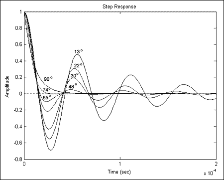
Figure 4. MATLAB step() command for closed-loop gain for varying phase margin.
Figure 4 shows the response of the controller and increasing overshoot and ringing as phase margin is decreased. Eventually full oscillations occur as the phase margin is reduced to near zero. The plus side to this approach is that, as the phase margin is reduced below 90°, the response time decreases. At a phase margin of around 72° the recovery is the fastest with 0% overshoot.
Generating Line and Load Transients
Generating line and load transient responses for power supplies must be done in a way that will generate relatively fast steps in line voltage and load current, and thus best approximate a true step function relative to the controller's bandwidth. This task might require special attention to the layout and component selection. The parasitic inductance, resistance, and capacitance of PC-board traces and components will act to limit the slew rates required when generating reasonably fast step responses with large switched currents.
The minimum rise time of the line or load step is determined by the loop bandwidth of the controller. A 1MHz controller should have a loop bandwidth of less then ½ the switching frequency, or 500kHz. When looking at the response of the controller, therefore, the rise time of the step required to fully test the controller's response should be fast enough to inject a frequency component of at least fSW/2. This can be related to the Fourier components of the transient because the slew rate of the transient will be set by the highest frequency component of the step. The maximum slew rate of a sinusoid (A x sin(ω)) is equal to the maximum value of the derivative, or simply (SLEW RATEMAX = A x ω). This results in a minimum rise time of 1/(π x fSW).
Once the rise time and the voltage or current step are known, a measure of the effects on the step from any parasitic inductance, resistance, and capacitance can be estimated. Suppose, for example, a 10A step in 200ns needs to be applied at the output. If there is 100nH of inductance between the output capacitor and the load, then the fastest rise time that can be reached (discounting any delays due to switching on the load) is 555ns. Clearly the parasitic inductance is critical. On the other hand, if a step of 10A in 10µs needs to be generated at the same output, then the limitations due to the inductance will only account for 5% of the total rise time.
Generating Line Transients
Fast line transients can be generated with two low RDS(ON) n-Channel MOSFETs switching between two DC power supplies. This is setup as described in Figure 5. During time A, Q1 pulls the power supply input to the 5V supply while Q2 disconnects the input from the 3V supply. During time B, Q1 disconnects the 5V supply and Q2 connects the input to the 3V supply. Note that the source of Q2 connects to the 3V supply while the drain of Q1 connects to the 5V supply. This somewhat unusual connection prevents the unwanted conduction of the MOSFETs body diodes. The gate drive for Q1 and Q2, (VGS), must be a threshold voltage above the drain-to-source voltage (VDS) to fully turn on the switch. This can pose problems with high-voltage inputs, although when dealing with 5V or lower systems, sufficient gate drive is readily available from function generators or MOSFET drivers. The MAX4428, for example, can source and sink up to 1.5A with 18V gate drive and has a complimentary output which drives both FETs out of phase.
If the input capacitor, CIN, does not need to be directly at the power supply's input, then CIN can be removed and CBP from Figure 5 becomes the power supply's input capacitor. This is beneficial when CIN is large and fast rise times are required at the input.
Parasitics
Parasitic inductance, resistance, and capacitance limit the clean waveform of the simulated step function. Figure 5 shows the important parasitics encountered when generating a line transient step. To source and sink the necessary large currents, the series resistance and inductance of the PC board, MOSFETs, and capacitors must be minimized. With the large capacitance and low resistance of the circuit, the step response becomes underdamped. This results in ringing (resonance) from the inductance and capacitance at the junction between MOSFETs and at the input to the power supply in Figure 5. Although the inductance cannot be reduced to zero, it can be reduced to a point where the resonant frequency is high enough to be negligible with the practical rise and fall times of the simulated step function.
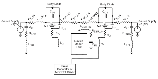
Figure 5. Line transient setup with parasitic components.
Power Source Bypassing
If the input capacitance, CIN, is inadequate or if CIN must be placed directly at the input to the supply for noise and/or layout reasons, the line voltage step must be generated across CIN. If this is the case, then a current

must be sourced and sinked into CIN to raise the voltage by ΔV in time Δt. When this is the case, the bypass capacitors, CBP, must be much larger than CIN and must be low RESR ceramic capacitors. This ensures that the voltage drop across RESR_ is minimized at the necessary currents required to charge and discharge CIN. Even with ceramic bypass capacitors, the inductance (LESL) can still pose a problem when dealing with fast rise times, or when CIN is large and requires a huge amount of current. Inductance of only a few nH will limit the current rise time needed for a reasonable CIN voltage step. If CIN is 100µF and ΔV is 1V, for example, then the supply must source 100A into CIN in order to step the voltage in 1µs. If there is 100nH of parasitic inductance between CBP and CIN, then it will take 2µs to raise CIN by 1V. Additionally, increased inductance will cause excessive overshoot or ringing, and cause the line transient not to represent the true step function desired. Inductance can be reduced by paralleling smaller value ceramic capacitors. The RESR and LESL of multiple capacitors are placed in parallel, thus reducing the total equivalent impedance. The distance from the bypass capacitors to the drains of the MOSFETs must also be minimized. PC-board traces for 1 ounce copper are on the order of 25mΩ/cm and 4.75nH/cm for 2mm wide traces. Short wide traces must be used to reduce the inductance and resistance seen between the bypass capacitors and the MOSFET drains.
MOSFETs
MOSFET selection is primarily focused on on-resistance (RDS_ON), package size, and gate capacitance. RDS_ON is important for the same reason as PC-board resistance and bypass capacitor ESR. Increased resistance limits the current that can be sourced and sinked into the input capacitance, CIN, and causes excessive voltage ripple due to the pulsed currents of switching power supplies. Finding a MOSFET with the lowest RDS_ON is especially important since RDS_ON will be the primary source of resistance in the capacitor charge and discharge path. In addition, MOSFET series inductance, which includes the drain-to-source inductance and the inductance of the internal bond wires and the leads, is another area on which we can focus to reduce the total inductance in series with the power supply.
Very low on-resistance MOSFETs normally have higher gate capacitance (CGS). As mentioned above, MOSFET drivers such as a MAX4428 can drive the several nFs of gate capacitance of even large MOSFETs. The trace lengths between the MOSFET driver and the gate must be kept short and wide to reduce the inductance and resistance, and to allow for the high currents that must be sourced and sinked to charge and discharge CGS. Once the inductance and resistance of the capacitor charge and discharge paths are minimized, the MOSFETs must be connected to either the power supply's input capacitance or, if possible, directly to the supply input. In the later case, the bypass capacitors for the power sources would also be the input capacitance. In either case, the connection from the MOSFETs to CIN, or from the MOSFETs to the power supply input, must be made as short as possible to minimize PC-board parasitic inductance and resistance.
Generating Load Transients
The best method for generating a load step at a power supply output is to use an n-Channel MOSFET as the load element (triode region). In this configuration the power supply output connects to the drain of the MOSFET, and the MOSFET source connects to GND. The power supplies load is adjusted by stepping the gate to source voltage, VGS. As long as VGS is larger than the MOSFET's threshold voltage, VT, and larger than the drain to source voltage, VOUT, then adjusting VGS will vary the RDS_ON of the MOSFET and thus the load current. To sense the current step, a low-inductance sense resistor must be used to avoid adding extra inductance in series with the load current path. This inductance will limit the rise time of the current step and cause ringing between the drain-to-source capacitance, CDS, and the parasitic trace inductance, LPARA. In this configuration the sense resistor becomes part of the load. Additionally, the MOSFET must be placed directly across the output capacitor, COUT, of the power supply under test. Smaller MOSFETs, or MOSFETs in parallel, can further reduce the parasitic inductance, LPARA.
The connection between the MOSFET gate and the pulse generator, or MOSFET driver, must be short and wide to minimize the trace inductance and resistance, RG and LG. Figure 6 shows the setup for the load transient with the addition of the parasitic components.
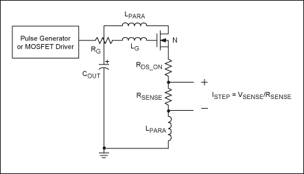
Figure 6. Load transient test with parasitics labeled.
Practical Examples
Load Transient
Figures 7, 8, and 9 show a 0 to 10A load transient using a MAX1960 voltage-mode buck and the circuit of the MAX1960 Evaluation Kit (see MAX1960EVKIT at www.maximintegrated.com). A high-frequency pole is added at COMP to reduce the gain above crossover. If this pole is brought in too low in frequency, the phase margin begins to reduce. Figure 7 shows the response with an open-loop crossover frequency of 42kHz and an unacceptable 2° of phase margin. In response to the load step, the power supply goes into continuous oscillations. As the pole is moved out in frequency, the phase margin increases. At 11° the oscillations become damped, as shown in Figure 8. With 90° of phase margin (Figure 9) the response at the output is that of an exponential, single pole.
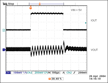
Figure 7. Loop response with an open-loop crossover frequency of 42kHz and an unacceptable 2° of phase margin.
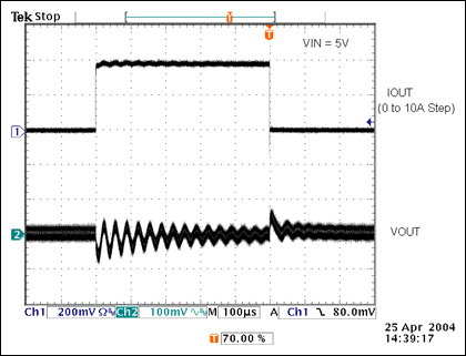
Figure 8. The response with 11° of phase margin shows damped oscillations.
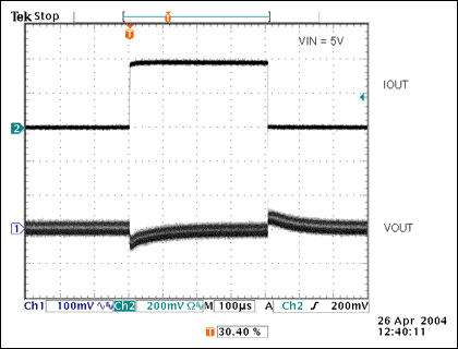
Figure 9. Loop response with 90° of phase margin is that of an exponential, single pole.
The load transient was generated using a single IRLR024N, n-Channel MOSFET with an on resistance of 65mΩ. The MOSFET was placed directly on top of one of the OUTPUT capacitors with a 37.5mΩ low-inductive sense resistor placed between the source and GND. The gate was stepped from 0 to 4V directly from a HP8112 pulse generator. Step responses from 0 to 10A in 200ns could be generated with virtually no overshoot or ringing.
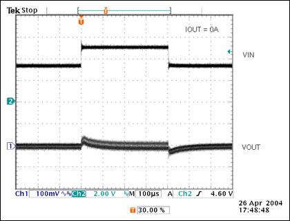
Figure 10. Line transient response for same circuit as in Figure 9.
Figures 10 shows a line transient response with the same circuit used for the plot in Figure 9. Here the input voltage is stepped from 3.3V to 5V. Two IRF3704, 9mΩ n-Channel MOSFETs switched between a 3.3V and 5V supply using the connection from Figure 5. Each switch was placed between the MAX1960's input and two paralleled 470µF Sanyo POSCAPs (6TPB470M). Rise times of 400ns with 250mV overshoot were developed to simulate the line step.


