Abstract
Switching regulators can replace LDOs (low-dropout linear regulators) forgenerating 1.5V/3A output from a 3.3V input. Switching regulators also provide an environmentally friendly \"green\" design that increases efficiency up to 87% over the wasteful 45% of LDO designs. Board space in existing LDO designs is typically limited, often too small for a switching regulator. The MAX8505 switching regulator with MOSFETs is packaged in a 16-pin QSOP and fits an LDO footprint.
Efficiency is becoming more valuable every day. With energy prices on the rise and the growing concern over global warming, designing "green" circuits with high efficiency provides lower-cost operation and reduces environmental impact.
In cost-sensitive applications, LDOs are the common choice for generating 1.5V/3A output from a 3.3V input. Due to the high power dissipation (5.4W) in the LDO, either a TO220 or D2PAC package must typically be selected. To reduce energy consumption, switching regulators have begun to replace LDOs in low-end server designs. However, board space in existing LDO designs is often limited and, in most cases, too small for a complete switching regulator. A D2PAC LDO regulator with two 1206 ceramic capacitors, for example, occupies about 18mm x 14mm. Fitting a switching regulator into such a small area is not an easy task, particularly if external MOSFETs are required.
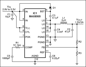
The MAX8505 is a high-frequency PWM step-down switching regulator with both high- and low-side MOSFETs in a 16-pin QSOP package (5mm x 6.5mm). The 1MHz switching frequency allows use of a small inductor and ceramic capacitors for both input and output filtering, thus resulting in a very small footprint. Figure 1 shows the complete MAX8505 circuit. It accepts either a 5V or 3.3V input, and generates a 1.5V at 3A output. Typical peak transient current is 5.6A. The major circuit components fit into a 16mm x 14mm footprint, achieving an even smaller footprint than LDOs. With a total dissipation of only 0.67W, the device conserves nearly 5W of the power compared to the LDO. Table 1 shows feedback resistor values for 0.9V, 1.5V, 2.0V, and 2.5V outputs.

Figure 1. MAX8505 internal switch step-down regulator circuit.
| VOUT | R3 | R2 |
| 0.9V | 10kΩ | 1.24kΩ |
| 1.5V | 10kΩ | 8.66kΩ |
| 2.0V | 10kΩ | 15kΩ |
| 2.5V | 10.5kΩ | 22.1kΩ |
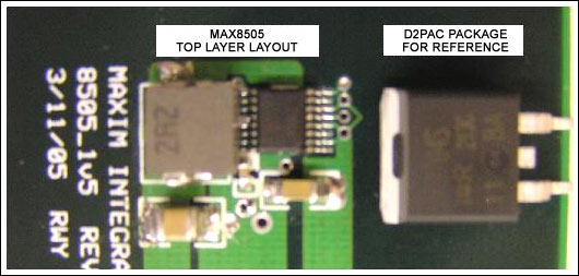
Figure 2 shows the top layer of the MAX8505 PCB layout with a D2PAC package positioned on the right for reference. The PCB top layer contains the largest components: the MAX8505, L1, C1, C2, and C4. Seven additional small (0603 package) components are placed on the opposite side of the board, but their placement is less critical.

Figure 2. Picture of the MAX8505 switching regulator with a D2PAC device on the side for comparison.
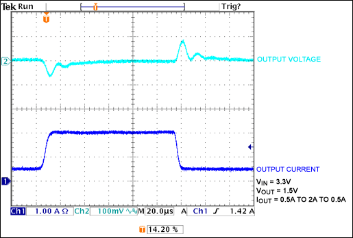
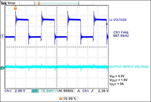
Table 2 compares power dissipation, footprint, and total external component count of the LM317, the MAX8505, and a typical controller with external MOSFETs. The MAX8505 requires the smallest board space and provides the highest efficiency. Step-load transient response is shown in Figure 3. Output ripple voltage, shown in Figure 4, is less than 10mV. Table 3 presents the bill of materials for the MAX8505.
| Parameters | LDO (LM317) | MAX8505 | Typical Controller IC |
| Efficiency (%) | 45.5 | 87 | 76 |
| Power Dissipation (W) | 5.4 | 0.67 | 1.42 |
| Total Components | 5 | 12 | 11* |
| Area (mm x mm) | 18 x 14, Single Side | 16 x 14, Double Side | – |
| Conditions: 3.3V to 1.5V at 3A, design for adjustable output | |||
| * 11 components are needed to achieve less than 10mV output ripple voltage. | |||

Figure 3. Step load-transient response: 0.5A to 2A back to 0.5A.

Figure 4. Lx switching waveform and the output ripple voltage.
| Designation | QTY | Description | Part Number |
| C1 | 1 | Input capacitor, 1206 | 10µF/6.3V |
| C2 | 1 | Output capacitor, 1210 | 47µF/6.3V |
| C3 | 1 | Decoupling capacitor, 0603 | 0.1µF/6.3V |
| C4 | 1 | Snubber capacitor, 0603 | 3300pF/50V |
| C5 | 1 | Compensation capacitor, 0603 | 220pF/50V |
| C6 | 1 | Decoupling capacitor, 0603 | 0.22µF/6.3V |
| R1 | 1 | Compensation resistor, 0603 | 51.1kΩ, 1% |
| R2 | 1 | Voltage set resistor, 0603 | See Table 1 |
| R3 | 1 | Voltage set resistor, 0603 | See Table 1 |
| L1 | 1 | 2.2µF/7A SMD inductor, 6.3mm x 6.2mm x 2.5mm | Toko |
| D1 | 1 | Small signal diode | 1N4148 or CMDSH-3 |
| IC1 | 1 | 3A internal switch regulator | MAX8505 |


