Do Passive Components Degrade Audio Quality in Your Portable Device?
Abstract
In an audio circuit, passive components define the gain, provide biasing and power-supply rejection, and establish DC-blocking from one stage to the next. Portable audio, for which space, height, and cost are usually at a premium, forces the use of passives with small footprints, low profiles, and low cost.
The audible effect of these devices is worthy of some examination, because poor component choice can significantly degrade the measured performance. Some designers assume that resistors and capacitors have no measurable effect on audio quality, but the nonlinear characteristics of many common passives used in the audio signal path can seriously degrade total harmonic distortion (THD). In some cases, the nonlinear contribution of passives exceeds that of active devices such as amplifiers and DACs, which are assumed by many designers to be the limiting factor in audio performance.
Sources of Nonlinearity
Capacitors and resistors both exhibit a phenomenon called voltage coefficient, in which a change in voltage across the component changes its physical characteristics and hence its value, to some degree. For example, a particular 1.00kΩ resistor with no voltage across it becomes a 1.01kΩ resistor when 10V is applied. That effect varies enormously according to the component's type, construction, and (for capacitors) chemistry. Voltage-coefficient information is sometimes available from the manufacturer as a graph, showing the percent change in capacitance vs. the percent of rated voltage.
The voltage coefficient of modern film resistors is very good, and usually below the level that is readily measured in the lab. Capacitors, on the other hand, can limit performance as a consequence of several departures from the ideal:
- Voltage coefficient: Described previously.
- Dielectric absorption (DA): A memory-like effect in which a discharged capacitor retains some of the charge previously stored on it.
- Equivalent series resistance (ESR): This can be frequency dependent, and can limit power output when series-coupling capacitors drive the low impedance of a headphone or speaker.
- Microphony: Some capacitors have a marked piezoelectric effect, in which physical stress and flexure of the capacitor generates a voltage across the terminals.
- Poor tolerance: For most large-valued capacitors (several µF and higher), accuracy is not tightly specified. Resistors, on the other hand, are readily and inexpensively specified for a tolerance of 1% or 2%.
The following discussion outlines a test method consisting of a simple test circuit and readily available audio test equipment that can quantify the undesired effects of capacitors in the audio signal path. The intent is not to pass judgement on particular sizes, voltage ratings, and case types, but to alert readers to the phenomena, show representative results, and offer a test method that allows meaningful comparisons and conclusions.
Test Description
Nonlinear AC effects are easily found in capacitors. The frequency response of analog audio (necessarily restricted) dictates that most circuit blocks include highpass, lowpass, or bandpass filter circuits, and that the nonlinearities of such filters can have real and measurable effects.
Consider a simple, highpass RC filter (Figure 1). At frequencies well above its -3dB cutoff, the capacitor's impedance is low with respect to that of the resistor. The application of a high-frequency AC signal develops very little voltage across the capacitor, so any change due to the voltage coefficient should be minimal. Signal current flowing through the capacitor, however, generates a corresponding voltage across the capacitor's ESR. Any nonlinear component of that ESR sums in at the appropriate level and can degrade THD.
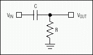
Figure 1. Simple highpass RC filter.
At and near the -3dB cut-off point, however, impedances of the capacitor and resistor are of the same order. The result is a significant AC voltage across the capacitor at a point in the response that imposes only minor attenuation on the input signal. Thus, any voltage-coefficient effects tend to peak around that point.
By focusing on THD at the -3dB cutoff, this test highlights nonideal behavior-primarily that due to the voltage coefficient. The test circuit is based on a highpass filter with -3dB cutoff at 1kHz and an audio analyzer (Audio Precision System One) that looks for any degradation of THD+N while various capacitors of differing construction, chemistry, and type are substituted. A 1µF capacitor value was chosen because it offers a wide choice of capacitor types for testing. It is loaded with a 150Ω resistor to form a headphone filter with nominal 1kHz cutoff. Note that the capacitor under test has no DC bias across it. Input and output have the same DC potential.
Polyester Capacitor and Reference Baseline
A plot of THD+N vs. frequency in Figure 2 shows the limit of resolution in the test setup, and also the minimal effects of a 25V through-hole polyester capacitor not typically used in portable designs. Little, if any, THD degradation due to voltage coefficient is apparent. Note that the polyester capacitor allows THD to rise below 1kHz, but the output signal is actually falling with a frequency below 1kHz, thereby reducing the ratio of signal-to-noise (plus distortion) registered by the analyzer. The key region is at and above 1kHz, where the polyester capacitor performs well—only slightly worse than the reference measurement.
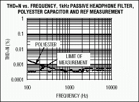
Figure 2. THD+N vs. frequency for a 1kHz highpass passive filter with polyester capacitor, compared to a reference measurement.
Tantalum Dielectric
Tantalum capacitors are often found in portable devices, usually for blocking DC voltage to a headphone and especially if more than a few µF are required. Another plot of THD+N vs. frequency in Figure 3 compares three variations of a popular SM tantalum capacitor with a traditional, through-hole "dipped" tantalum capacitor readily available in the lab. The capacitors again have 1µF values; only their physical dimensions (case size) and voltage ratings differ. See Table 1. No DC bias was applied to the capacitors during this test.
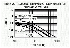
Figure 3. Comparison of THD+N vs. frequency for various tantalum capacitors in a 1kHz highpass passive filter.
| Value | Case Size L × W (mm) | Voltage Rating (V) |
| 1µF | A (3.2 × 1.6) | 25 |
| 1µF | B (3.5 × 2.8) | 35 |
| 1µF | C (6.0 × 3.2) | 50 |
Ceramic Dielectric
Ceramic capacitors are often used for AC-coupling between audio stages, and in bass-boost and filtering circuits. Various dielectric types are available, as Figure 4 illustrates, based on the components listed in Table 2.
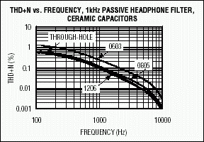
Figure 4. Comparison of THD+N vs. frequency for various ceramic capacitors in a 1kHz highpass passive filter.
| Value | Case Size | Voltage Rating (V) | Dielectric Type |
| 1µF | 0603 | 10 | X5R |
| 1µF | 0805 | 16 | X7R |
| 1µF | 1206 | 16 | X7R |
Figure 4 also depicts the performance of a through-hole ceramic capacitor selected from a random assortment of lab components. The worst result is just 0.2% THD at the -3dB point for the X5R dielectric. To put it in perspective, that performance equates to distortion at the -54dB level. The THD for most 16-bit audio DACs and CODECs, with respect to full scale, is at least an order of magnitude better than this. Note that C0G dielectrics can exhibit very low voltage coefficients, but at this time their capacitance ranges are restricted to values near 0.047µF and below. These tests were based on 1µF capacitors, so C0G types were not included.
How to Avoid Capacitor Voltage-Coefficient Effects
Figure 5 shows a line-input topology whose novel AC-coupling configuration allows a much lower valued input capacitor than that of a traditional configuration. The input capacitor in this example (C1) is 0.047µF, which can be specified as a ceramic with C0G dielectric in a 1206 case size—a configuration that minimizes the THD contribution from voltage-coefficient effects. DC feedback for the op amp (which should be a device with low input-bias current, such as the MAX4490) is provided by the two 100kΩ resistors. The effect of the DC-feedback path at audio frequencies is attenuated by C2 and R5, so the majority of the feedback is from R1 and R2 through C1. With the values shown, the -3dB point is set at 5Hz.
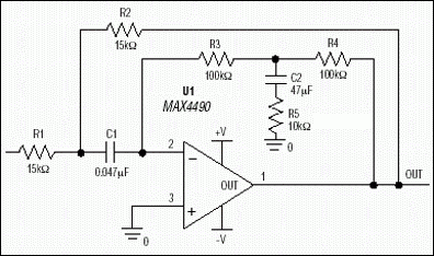
Figure 5. This novel line-input stage reduces degradation due to voltage-coefficient effects. Including the traditional AC-coupling capacitor inside the amplifier's error path lowers the value of that capacitor, and enables the use of C0G capacitors in portable designs.
This type of compound feedback ultimately has a first-order LF rolloff, but can be tuned for a 2nd-order response around the highpass cutoff frequency. Consequently, pay careful attention to overshoot and peaking when adjusting the component values from those shown in Figure 5. Values in the example approximate a maximally flat highpass function. This circuit principle can easily be adapted to quasidifferential (ground-sensing) and fully differential input stages.
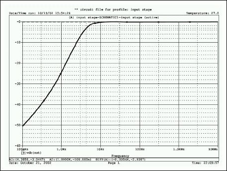
Figure 6. Frequency response for the circuit in Figure 5 shows a smooth rolloff below 10Hz with the -3dB point at 5Hz. The ultimate rolloff rate with decreasing frequency is 20dB/decade.
The stereo headphone driver IC shown in Figure 7 (MAX4410) features an innovative technology called DirectDrive®, in which the output bias, powered from a single positive supply, is set at 0V to allow direct DC-coupling to the headphones. Several advantages follow:
- Large DC-blocking capacitors (100µF–470µF, typ) are eliminated, which removes a significant THD contribution based on voltage coefficients.
- The lower -3dB cutoff, now defined by the input capacitor and input resistor, is around 1.6Hz with the values shown in Figure 7, but a -3dB point of 1.6Hz in standard AC-coupled headphone drivers for 16Ω headphones requires about 6200µF. In addition, the low-frequency response is no longer load dependent.
- Eliminating the large-case capacitors saves a significant amount of PCB area. Such capacitors are expensive when compared with the 1µF and 2.2µF ceramic compacitors required by MAX4410 charge-pump circuitry.
- To enable the outputs to sink and source load current with a ground-referenced load, the chip generates an internal negative supply for the amplifier. Because that supply (PVSS) is an inverted version of the positive supply (VDD), the available voltage swing at the output (almost 2VDD) is twice that of a traditional single-supply, AC-coupled headphone driver.
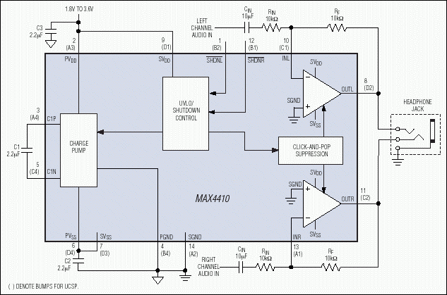
Figure 7. In this typical application circuit for the MAX4410 stereo headphone driver, setting CIN to 10µF restricts any voltage-coefficient effects to subaudible frequencies. Large-valued coupling capacitors at the output are not necessary.
In this example, it has been a relatively simple matter to minimize the voltage-coefficient effect of input capacitors on audio bandwidth by oversizing those capacitors. Given a 10kΩ input resistor, choose a 10µF ceramic for CIN. That combination places the -3dB point at 1.6Hz, so the worst effects due to voltage-coefficient nonlinearity are at least an order of magnitude below the lowest audible frequencies being reproduced.
Regarding larger valued capacitors, Figure 8 two types of 100µF capacitors used with a 16Ω resistor in forming a passive highpass filter. At the 100Hz, -3dB frequency, both types contribute significant THD due to the capacitors' voltage coefficient. The 100µF tantalum contribution to THD+N is 0.2% at the -3dB cutoff, which is equal to the worst-performing ceramic device in Figure 4. Eliminating those devices from the audio path using Analog's DirectDrive components, or similar techniques, improves the audio quality significantly and notably at low frequencies. In Figure 8, a MAX4410 is used to derive the reference plot (limit of measurement).
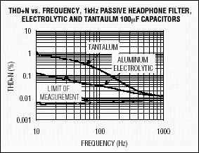
Figure 8. THD+N vs. frequency for large-valued, 100µF capacitors driving a 16Ω load. Both types (tantalum and aluminum electrolytic) contribute heavily to THD at the nominal -3dB point of 100Hz. No such output-coupling capacitors are required with Analog's DirectDrive headphone amplifiers.
Summary
Passive components can add real, measurable degradation to an analog audio path. Those effects can be easily examined and assessed using standard audio test equipment. Of the capacitor types tested, aluminum-electrolytic and polyester capacitors give the lowest THD. X5R ceramics give the poorest THD.
When choosing active components, take care to minimize the number of AC-coupling capacitors in analog audio stages. For example, use differential signal paths or DirectDrive components for headphone feeds (e.g., MAX4410). When possible, design audio circuitry with low capacitance values in which C0G or PPS dielectrics can be used. To reduce voltage-coefficient effects in AC-coupled audio stages, restrict potential problems to the subaudio frequencies by lowering the -3dB point much more than necessary, by 10×, for example.


