Designing Power Supplies for Industrial Functional Safety— Part 1: What IEC 61508 Tells Us
Designing Power Supplies for Industrial Functional Safety— Part 1: What IEC 61508 Tells Us
Jul 15 2025
Read other articles in this series.
Abstract
A power supply unit is one of the most crucial components in an electronics system as its operation can affect the entire system’s functionality. In the context of industrial functional safety as in IEC 61508, power supplies are considered elements and supporting services to electrical/electronic/programmable electronic (E/E/ PE) safety-related systems (SRS) as well as other subsystems. With the IEC 61508’s three key requirements for functional safety (FS) compliance alongside recommended diagnostic measures, developing power supplies for industrial FS can be tiresome. For this reason, this first part of the series discusses what the basic functional safety standard states about power supplies.
Introduction
This first part of this series on power supply design in the context of industrial functional safety focuses on insights about the safety requirements for such elements of electrical/electronic/programmable electronic (E/E/PE) safety-related systems (SRS). This is accomplished by showing what the basic functional safety standard requires from power supplies.
Power Supplies in E/E/PE Safety-Related Systems
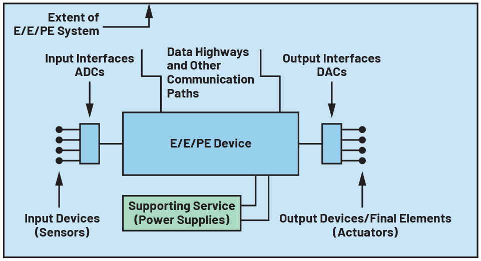
The IEC 61508-4 defines E/E/PE systems as systems used for control, protection, or monitoring based on one or more E/E/PE device. This includes all elements of the system such as power supplies, sensors and other input devices, data highways and other communication paths, and actuators and other output devices. Meanwhile, a safety-related system is defined as a designated system that both implements the required safety functions necessary to achieve or maintain a safe state for the equipment under control (EUC) and is intended to achieve, on its own or with other E/E/PE SRS and other risk reduction measures, the necessary safety integrity for the required safety functions. This is shown in Figure 1 where power supplies also serve as an example of supporting services to an E/E/PE SRS aside from the hardware and software required to carry out the specified safety function.

Power Supplies and Common Cause Failures
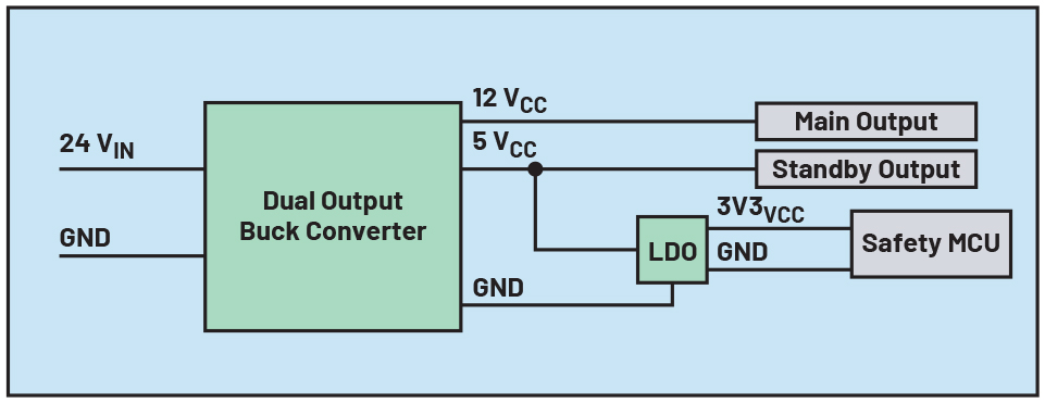
The basic functional safety standard defines common cause failure (CCF) as a failure that is the result of one or more events, causing concurrent failures of two or more separate channels in a multiple channel system, leading to system failure. One example is a power supply failure that can result in multiple dangerous failures of the SRS. This is shown in Figure 2 where a failure in the 24 V supply, assuming the 24 V input becomes shorted to its outputs 12 VCC and 5 VCC, will result in a dangerous failure of the succeeding circuits.

CCFs are important to consider when complying with functional safety as it affects compliance to the IEC 61508’s three key requirements: systematic safety integrity, hardware safety integrity, and architectural constraints. These standard cited requirements regarding CCF and power supplies in certain circumstances are shown here:
- IEC 61508-1 Section 7.6.2.7 takes the possibility of CCF into account when allocating overall safety requirements. This section also requires that the EUC control system, E/E/PE SRS, and other risk reduction measures when treated as independent for the allocation shall not share common power supplies whose failure could result in a dangerous mode of failure of all systems.
- Similarly, under synthesis of elements to achieve the required systematic capability (SC), IEC 61508-2 Section 7.4.3.4 Note 1 cites ensuring that there’s no common power supply failure that will cause a dangerous mode of failure of all systems is a possible approach to achieve sufficient independence.
- For integrated circuits with on-chip redundancy, IEC 61508-2 Annex E also cites several normative requirements including separation of input and outputs such as power supply among others, and use of measures to avoid dangerous failures caused by power supply faults.
While these clauses prohibit sharing common power supplies whose failure could cause a dangerous mode of failure of all systems, implementing such practice when designing a system will result in an increased footprint with greater board size and cost. One way to still use common power supplies is by employing sufficient power supply monitoring. By doing this, dangerous failures brought by the power supply to an E/E/PE SRS can be reduced to a tolerable level, if not eliminated, in accordance with the safety requirements. More discussion about how effective power supply monitoring can solve common cause failures can be found in the blog post “Functional Safety for Power.”
Power Supply Failures and Diagnostics
With the need to detect failures in the power supply, the basic functional safety standard specifies requirements and recommendations to address both systematic and random hardware failures.
In terms of the requirements for control of systematic faults, IEC 61508-2 Section 7.4.7.1 requires the design of E/E/PE SRS to be tolerant against environmental stresses including electromagnetic disturbances. This clause is cited in IEC 61508-2 Table A.16, which describes some measures against defects in power supplies—voltage breakdown, voltage variations, overvoltage (OV), low voltage, and other phenomena—as mandatory regardless of SIL level. This is shown in Table 1.
| Technique/Measure | SIL 1 | SIL 2 | SIL 3 | SIL 4 |
| Measures against voltage breakdowns, voltage variations, overvoltage, low voltage, and other phenomena such as AC power supply frequency variation that can lead to dangerous failure | M low |
M medium |
M medium |
M high |
IEC 61508-2 Table A.1, under the discrete hardware component, shows the faults and failures that can be assumed for a power supply when quantifying the effect of random hardware failures. This is shown in Table 2. Meanwhile, IEC 61508-2 Table A.9 shows the diagnostic measures recommended for a power supply along with the respective maximum claimable diagnostic coverage. Table 3 shows this with more details from IEC 61508-7 Section A.8.
Both Table 2 and Table 3 are useful when doing a safety analysis as failure modes per component and diagnostic coverage of diagnostic techniques employed are inputs to the calculation of lambda values, thus the SIL metric: probability of dangerous failure and safe failure fraction (SFF).
| Component | Low (60%) |
Medium (90%) |
High (99%) |
| Power supply | Stuck-at | DC fault model Drift and oscillation |
DC fault model Drift and oscillation |
| Diagnostic Measure | Aim | Description | Max DC Considered Achievable |
| OV protection with safety shut-off | To protect the SRS against OV. | OV is detected early enough that all outputs can be switched to a safe condition by the power-down routine or there is a switch-over to a second power unit. | Low (60%) |
| Voltage control (secondary) | To monitor the secondary voltages and initiate a safe condition if the voltage is not in its specified range. | The secondary voltage is monitored and a power-down is initiated, or there is a switch-over to a second power unit, if it is not in its specified range. | High (99%) |
| Power-down with safety shut-off | To shut off the power with all safety critical information stored. | OV or undervoltage (UV) is detected early enough so that the internal state can be saved in nonvolatile memory if necessary, and so that all outputs can be set to a safe condition by the power-down routine, or there is a switch-over to a second power unit. | High (99%) |
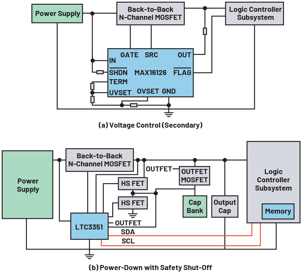
Figure 3a shows an example of a voltage control diagnostic measure. In this example, the power supply of the logic controller subsystem, typically in a form of a postregulator or LDO, is monitored by the MAX16126. Any out-of-range voltage detected by the supervisor, whether it be OV or UV, will result in the disconnection of the logic controller subsystem, composed of microcontroller and other logic devices, from the power supply as well as assertion of the MAX16126’s FLAG pin. With this, the logic controller subsystem can be switched to a safe condition. Similarly, this circuit can also be used as an OV protection with safety shut-off diagnostic measure if UV detection is not present.
On the other hand, Figure 3b shows an example of a power-down with safety shut-off diagnostic measure. In this example, the LTC3351’s hot swap controller connects the power supply to the logic controller subsystem while its synchronous switching controller operates in step-down mode, charging a stack of supercapacitors. If the power supply goes outside the OV or UV threshold voltages, the LTC3551 will disconnect the logic controller subsystem from the power supply and the synchronous controller will run in reverse as a step-up converter to deliver power from the supercapacitor stack to the logic controller subsystem. This will give enough time to the logic controller subsystem to save the internal state to a nonvolatile memory, and so that all outputs can be set to a safe condition by the power-down routine.

Power Supply Operation
Aside from CCF, power supply failures, and recommended diagnostic measures, the IEC 61508 also expressed the importance of power supply operation in the E/E/PE SRS. This can be seen in the sixth part of the standard, Annex B.3, discussing the use of the reliability block diagram approach to evaluate probabilities of hardware failure assuming constant failure rate. Aside from the scope of the sensor, logic, and final element subsystems, power supply operation is also included—this is shown in the following examples.
- When a power supply failure removes power from a de-energize-to-trip E/E/PE SRS and initiates a system trip to a safe state, the power supply does not affect the PFDavg of the SRS.
- If the system is energized-to-trip or the power supply has failure modes that can cause unsafe operation of the E/E/PE SRS, the power supply should be included in the evaluation.
Such assumptions make power supply operation in an E/E/PE SRS critical as it can determine whether the power supply can affect the calculation for the probability of a dangerous failure— which is one of the IEC 61508’s key requirements.
Conclusion
This article provided insights regarding the basic functional safety standard’s normative and informative requirements for an E/E/PE safety-related system’s power supply. This was done by first tackling the role of the power supply in an E/E/PE SRS. A discussion of common cause failures, which prohibit the use of common power supplies, then demonstrated how the use of power supply monitoring eliminates CCFs. Requirements regarding systematic and random hardware failures pertaining to power supplies were also shown alongside the recommended diagnostic measures for power supplies. Finally, depending on the power supply operation—de-energize-to-trip or energize-to-trip—the probability of a dangerous failure of the SRS can be affected by the power supply was also covered.
References
Foord, Tony and Colin Howard. "Energise or De-Energise to Trip?" Measurement and Control, Vol. 41, No. 9, November 2008.
IEC 61508 All Parts, Functional Safety of Electrical/Electronic/Programmable Electronic Safety-Related Systems. International Electrotechnical Commission, 2010.
Meany, Tom. “Functional Safety for Power.” Analog Devices, Inc., March 2019.
About the Authors
Bryan Angelo Borres is a TÜV-certified functional safety engineer who focuses on industrial functional safety. As a senior power applications engineer, he helps component designers and system integrators design
Noel Tenorio is a product applications manager in the Industrial, Power, and Precision Group handling high performance supervisory products at Analog Devices Philippines. He joined ADI in August 2016. Prior to ADI, he
Related to this Article
Products
PRODUCTION
Load-Dump/Reverse-Voltage Protection Circuits
RECOMMENDED FOR NEW DESIGNS
Hot Swappable Supercapacitor Charger, Backup Controller and System Monitor
Industry Solutions
Product Categories


