Data Backup Solution for 1mm, Low Profile Industrial Applications
Data Backup Solution for 1mm, Low Profile Industrial Applications
Aug 25 2015
Introduction
Data backup and retention during a power interruption is required in a wide variety of industrial and automotive applications, where emergency backup power supplies (such as a UPS) may be unfeasible. For example, a vehicle may need to transmit geographical coordinates and the vehicle ID during an abrupt battery disconnect due to a catastrophic failure. On a more regular basis, performance data is required during vehicle maintenance, troubleshooting and repair work, often performed with a disconnected battery. In complex industrial metal machining equipment, it’s paramount to store the positions and states of multiple tools during a power disconnect to prevent equipment failure as power restored. Likewise, data retention and backup is important in oil and gas exploration industry, where it is widely used in vast communication networks of mining companies, which can often experience power failures and brownouts. Telecom companies require uninterrupted access to data at all levels of their systems.
Low Profile Data Backup Power Supply
Industrial and automotive applications are often distinguished from typical consumer electronics by their lack of stable, high quality voltage sources. In automotive environments, a 12V nominal voltage rail can change from 5V to above 50V during the cold starts and load dumps. The 24V equipment bus used in factories and plants suffers voltage spikes and brownouts just from turning on/off electrical motors and solenoids.
Industrial applications, however, do share something in common with consumer electronics: the trend toward increased portability and mobility. Space is increasingly limited for electronics inside modern industrial equipment. The volume, in particular, the thickness, of a data storage unit is at premium in industrial assemblies and modules. With that in mind, the solution here aims to minimize the profiles of the selected components. Table 1 shows two passive component group options, arranged by thickness: 1mm and 2.5mm. The required semiconductor parts are not listed because the controllers, MOSFETs and resistors do not exceed 1mm thickness.
| L1 | L2 | CS1 | CIN1 | |
| Vendor | Wurth-El | Wurth-El | CAP-XX | TDK |
| 1 mm | 74437321100 | 74437321056 | 2 x HS103F | 2 X C3216JB1H475K085AB |
| 2.5 mm | 74437334100 | 74437334056 | HS206F | C3225X7R2A225K230AB |
This article presents a low profile solution for designing energy storage circuit able to supply data backup circuitry or wireless data transmission in situations where input voltage changes in extremely wide range from 5V to 60V with possible input voltage interruption all together.
Figure 1 shows the solution based on the LTC3110[1], bidirectional buck-boost regulator and supercapacitor charger. A converter based on this part (SCCH) actually charges the storage capacitor when the input voltage is present and provides a regulated system output during power interruption. Under normal operation conditions (5V–60V input supply present), sensitive electronic loads and the LTC3110 are supported by a step-down converter (SDC) based on the LTC3891[2].
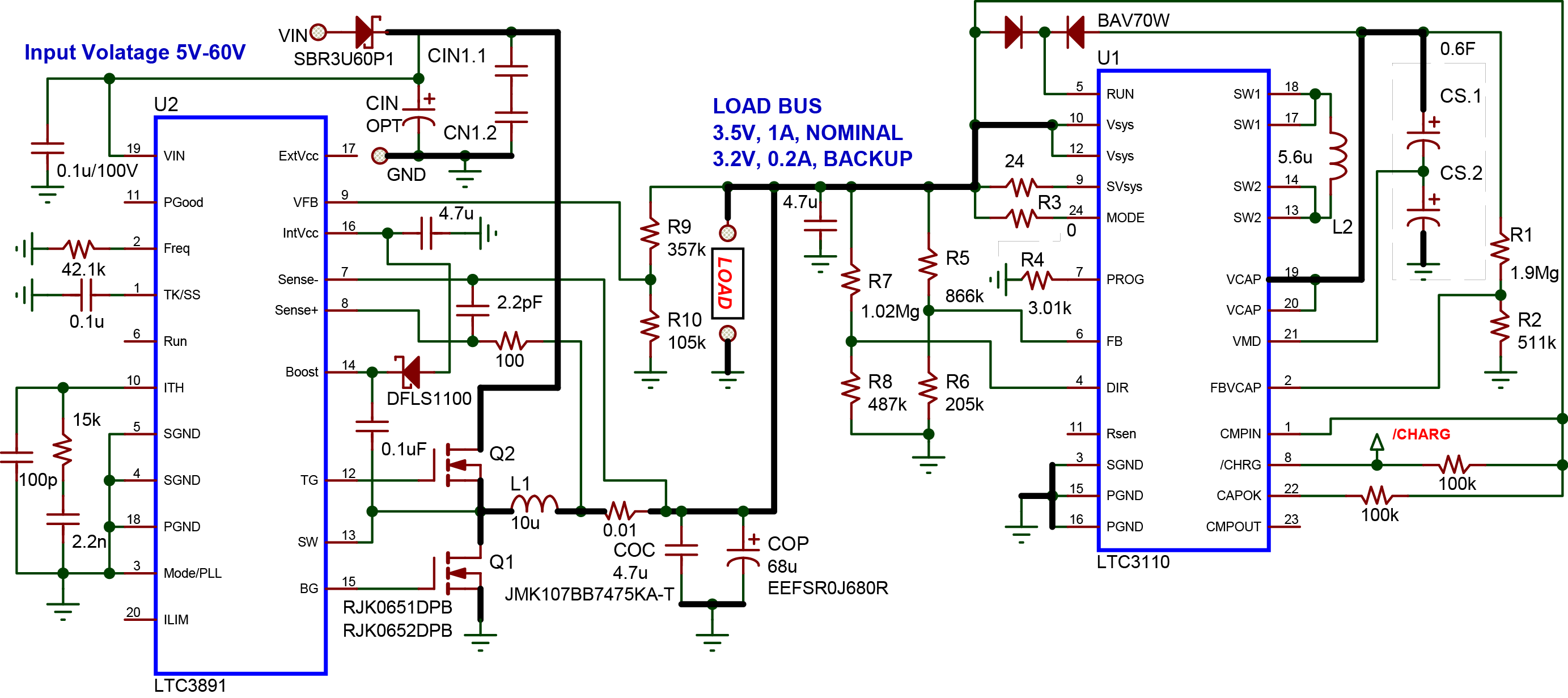
Figure 1. Industrial/automotive data backup supply using all low profile components
The LTC3891 is a low quiescent current, buck converter featuring a wide input voltage range extending from 4.5V to 60V. Its 60V upper limit minimizes the volume required for system protection circuitry, practically eliminating need for traditional transient voltage suppressor diodes (TVS). The SDC keeps system voltage within 3.3V bus rail limits, which covers 3.1V–3.6V voltage range[3][4]. The load voltage remains in this range regardless of input voltage swings.
If the input voltage is disconnected, the SCCH takes over, providing the regulated 3.3V rail. The LTC3891 supplies 3.5V to the system bus under normal circumstances; the LTC3110 supplies 3.2V when it registers a power failure and supports the load. These supply voltages are well within the recommended limits for 3.3V logic power supplies[5]. The /CHRG flag can be used to alert digital systems to disconnect irrelevant loads and begin data backup or wireless transmission.
The pin settings for the SCCH and SDC converters are summarized as follows:
- Divider R1, R2 sets End-of-Charge Threshold of Supercapacitor CS
- Resistor R3 defines mode of operation, tied to GND if used in the Burst mode
- Resistor R4 defines input current level during the charging
- Divider R5, R6 sets load voltage during the backup
- Divider R7, R8 sets the switchover voltage level
- Divider R9, R8 sets the load voltage if the input voltage is present.
Circuit Functionality
Waveforms and efficiency data are shown in Figures 2 - 5. Figure 2 shows the beginning of switchover process; with the input voltage disconnected, the SDC is turning off while the SCCH is turning on. Figure 3 illustrates the waveforms for the duration of data backup. Note that the VLOAD voltage stays at its preset SCCH value, even with the supercap voltage varying from above to below this level. Figure 4 demonstrates the ability of the LTC3110 to balance voltage of two series-connected supercapacitors as they are charged—VCAP is always twice VMID. Figure 4 also shows the LTC3110 regulating its input current (IV(SYS) used for charging) at a specified level, in this case, 1A
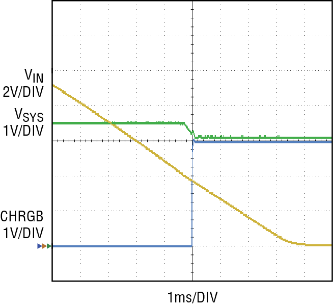
Figure 2. Switchover from normal supply to supercapacitor-based backup supply
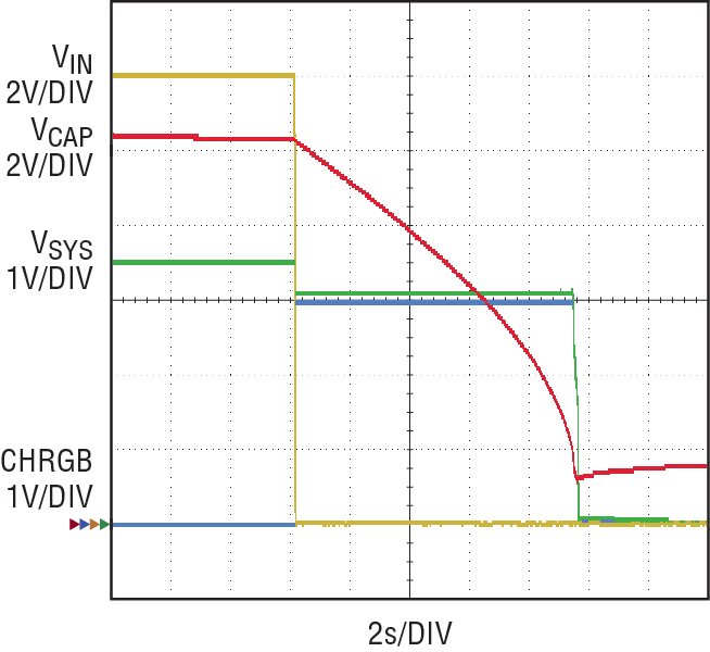
Figure 3. Duration of data backup when VIN is lost
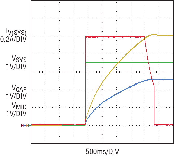
Figure 4. Supercap charging and balancing. IV(SYS) is current from LTC3891 converter to LTC3110.
Efficiency curves of the SCCH converter are shown in Figure 5. VCAP was forced to 3.3V during the test and the load varied in 0.5A range.
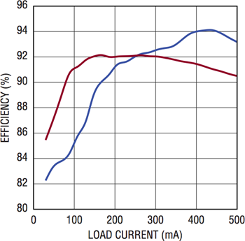
Figure 5. Efficiency
The following equations can be used for a rough estimation of storage capacitance and holdup time. (If more accurate results are required, see the supercapacitor documentation 3,4.)
Energy stored in supercapacitor:

Energy required to supply load for holdup time TH
![]()
Holdup time:

Conclusion
LTC3891 and LTC3110 are highly integrated, high performance controllers, which can be combined in a low profile solution for data retention and backup in automotive and industrial applications.
About the Authors
Victor Khasiev was a senior applications engineer at ADI with extensive experience in power electronics both in ac-to-dc and dc-to-dc conversion. He holds two patents and has written multiple articles. These articles are r...


