
Overview
Design Resources
Evaluation Hardware
Part Numbers with "Z" indicate RoHS Compliance. Boards checked are needed to evaluate this circuit.
- MAXREFDES277# ($615.25) Two-Channel IO-Link Master in Pmod Form Factor
Description
The MAXREFDES277# is a dual-channel IO-Link® master reference design optimized for quick prototyping. This design uses the Technologie Management Gruppe (TMG TE) IO-Link master stack for the MAX14819A IO-Link master transceiver and is both an evaluation model for an IO-Link master as well as an IO-Link sensor/actuator development and test system. Two IO-Link ports allow for simultaneous testing of up to two different sensors or actuators.
In this design, an STM32™ low-power microcontroller interfaces between the MAX14819A and the control board. The MAX14819A is a dual-channel IO-Link master transceiver with integrated framers and L+ supply controllers. Integrated L+ controllers are used to supply power to connected IO-Link devices. The MAX14819A integrated IO-Link framer offloads time-critical tasks from the microcontroller, easing prototyping and software requirements.
Peripheral module (Pmod™) interface is an open standard written by Digilent, Inc., and is typically used for quick development and prototyping. The MAXREFDES277# with its Pmod and non-standard IO-Link connectors is optimized for this type of functionality. In lieu of the standard M12 connectors used in IO-Link, the MAXREFDES277# uses two small on-board connectors with L+, L-, and IO-Link connections to maintain a small size board.
The board ships with two M12-to-wire IO-Link cables required to connect IO-Link devices (e.g., sensors and/or actuators) to the MAXREFDES277# master board. An AC-to-DC (24V DC/1A) power supply, capable of providing the 24V power to the on-board MAX14819A IO-Link master transceiver and any connected sensors or devices, is also included.
Connecting the MAXREFDES277# to any Analog Devices, Inc., IO-Link device reference design, with the associated software, allows for easy evaluation.
Design files and sample MicroPython software are available in the Design Files. The board is also available for purchase.
Features & Benefits
- IEC 61131-9 Compliant
- Pmod Form Factor
- Optimized for Use with Trinamic MicroPython TMCM-0960-MotionPy V21
Applications
Markets and Technologies
Parts Used
Details Section
Advanced factory automation solutions (i.e., Industry 4.0) require an increasing number of smart sensors and smart actuators, which are typically controlled using IO-Link point-to-point serial communication between the sensor/actuator and controller (master). As a leading provider of IO-Link device transceiver and master transceiver ICs, Analog Devices also provides complete reference design solutions to help customers improve their time to market. These proven designs cover all the hardware and software requirements needed for compliance with the IO-Link standard.
IO-Link is the first open, field bus agnostic, low-cost, point-to-point serial communication protocol used for communicating with sensors and actuators that has been adopted as an international standard (IEC 61131-9). IO-Link standardizes interoperability of industrial equipment from all over the world. IO-Link can function directly from a PLC or be integrated into standard field buses, quickly making it the defacto standard for universally communicating between IO-Link masters like the MAXREFDES277# and smart IO-Link devices.
With this reference design and firmware, the MAXREFDES277# IO-Link master design allows the user to communicate with connected IO-Link industrial actuator or sensor equipment and gives the end user total flexibility at the factory floor level to simplify equipment installation and commissioning.
The complete reference design fits on a 3.4in × 0.8in (86mm × 20mm) printed circuit board (PCB) and connects to any 3.3V Pmod connector. Firmware provided for the MAXREFDES277# has been designed for use with the MotionPv v2.1 (TCM-0960) MicroPython board.


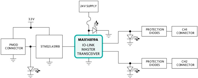
The MAXREFDES277# integrates the MAX14819A IO-Link master transceiver and is designed to be used with a Pmod-compatible controller board. Up to two IO-Link devices (sensors and/or actuators) can be connected to the MAXREFDES277# simultaneously, for easy IO-Link prototyping and evaluation (Figure 1).


The MAX14819A IO-Link master transceiver is compliant with the IO-Link version 1.1 physical layer specification. It integrates the high-voltage functions commonly found in IO-Link masters including two low-power sensor supply controllers with advanced current limits and reverse polarity protection. Operation is specified for normal 24V supply voltages, ranging up to 36V. Transient protection is simplified due to high voltage tolerance (i.e., 65V absolute maximum rating for the I/O pins without the integrated TVS diodes).
The MAX14819A features integrated UART frame handlers and FIFOs to simplify time critical control of all IO-Link M-sequence frame types. Additionally, the MAX14819A integrates an establish-communication sequencer to simplify wake-up management.
The MAXREFDES277# uses a low-power STM32 microcontroller to interface between the MAX14819A and the control board. The TMG TE IO-Link master stack for the MAX14819A ensures that communication between the controller and connected devices is IO-Link-compliant. The STM32 microcontroller limits the reference design operating temperature range from -40°C to +85°C, however the MAX14819A can operate over the -40°C to +125°C temperature range.
Power for the STM32 microcontroller is supplied from the control board through the Pmod connector. An external 24V supply is required to power the MAX14819A and any connected IO-Link devices.
The SMBJ36A protection diodes on the board are intended to provide protection against transient events that may occur during normal use while prototyping and do not provide reverse polarity protection against miswiring faults. Higher-level protection diodes may be required for large transient events (surge, ESD, and EFT/burst) on Channel A and Channel B. This board was tested to survive up to ±1kV/42Ω surge, referenced to GND. Analog Devices recommends replacing the current diodes with Littelfuse™ 1.5SMB47A for high-level surge and EFT/burst protection.
The MAXREFDES277# communicates with a host controller using an SPI interface, which is accessible on the J1 connector. The SPI connections correspond to the PMOD1 and PMOD2 connectors on the TMCM-0960-MotionPy V21 board. Pin connections are shown in Table 1.
| MAXREFDES J1 Connector Pin Number | Pin Number on TMCM-0960 PMOD1/PMOD2 Connector | TMCM-0960 Signal |
| 1 | 1 | CS01 |
| 2 | 3 | SPI1_MOS1 |
| 3 | 5 | SPI1_MISO |
| 4 | 7 | SPI1_SCK |
| 5 | 9 | GND |
| 6 | 11 | +3.3V |
| 7 | 2 | CS02 |
| 8 | 4 | GPO1* |
| 9 | 6 | GPO2* |
| 10 | 8 | GPO3* |
| 11 | 10 | GND |
| 12 | 12 | +3.3V |
*These pins are not connected on the MAXREFDES277# PMOD.
The MAXREFDES277# ships with the STM32 microcontroller preprogrammed with the TMG TE IO-Link master stack. This IO-Link master interface includes basic functionality for master module evaluation including an IO-Link autorun mode for startup, process data transfers, ISDU write and read functionality, device events and port event notifications.
Note that the stack that comes preprogrammed on the SMT32 microcontroller is not available as source code. Any licenses associated with this stack are available for use with the MAXREFDES277# for evaluation purposes only. Contact TMG TE directly to purchase stacks and licenses for use in final applications.
Optimized for the Trinamic MicroPython TMCM-0960-MotionPy V21 board, sample MicroPython code to connect the MAXREFDES277# to connected IO-Link devices can be downloaded from the Analog Devices website:
Restrictions and Warnings for Analog Devices Reference Design Use
The MAXREFDES277# and associated software is designed to evaluate the performance of the MAX14819A but is not intended to be deployed as-is into an end product in a factory automation system.
The MAXREFDES277# is not for use in functional safety or safety-critical systems.
To test the MAXREFDES277#, Trinamic MicroPython TMCM-0960-MotionPy V21 board and any IO-Link-compliant device.
Required Equipment
Supplied by Analog Devices
- MAXREFDES277#
- 24V AC-to-DC power adapter
- Two IO-Link wire-to-M12 connector cables
- MicroPython sample code zip file (uPython_sd_cardxxx.zip)
User Supplied
- Trinamic MicroPython TMCM-0960-MotionPy V21
- USB-A to USB-C cable
- 8Gb or smaller microSD card (formatted for FAT32)
- MAXREFDES164# or other IO-Link device
- Windows® PC with a USB port
- SSH Client Serial Terminal software such as Putty or CoolTerm. For this example, we use CoolTerm.
- Download and unzip the uPython_sd_cardxxx.zip file from the Analog Devices website.
- Insert the microSD card in the Trinamic MicroPython TMCM-0960-MotionPy V21 (MicroPython) board and connect the MicroPython board to the PC using a USB-A to USB-C cable.
- The microSD card shows up as an additional USB drive on the PC.
- Copy the entire contents of the uPython_sd_cardxxx file to the microSD card.
- Disconnect the MicroPython board from the PC.
- The MAXREFDES277# comes with two M12-to-wire IO-Link cables and two mating connectors for J2 and J3. Connect the L+, C/Q, and L- wires of each IO-Link cable to the mating connectors. Connect the brown wire of the cable to the L+ connector terminal. Connect the black wire of the cable to the C/Q connector terminal. Connect the blue wire of the cable to the GND connector terminal.
- Connect the MAXREFDES164# to Channel A on the MAXREFDES277# using the wire-to-M12 connector cables.
- Connect the 24V power supply to the MAXREFDES277# board and verify that LED2 turns on.
- Connect the MAXREFDES277# IO-Link master board to the MicroPython board. All LEDs on top of the board turn on.
- Connect the MicroPython board to the PC using a USB-A to USB-C cable. Figure 2 shows the complete hardware setup.

Figure 2. MAXREFDES277# system connection.
- Open the serial terminal software and configure for serial communication (Figure 3).
- Click OK (or Open) to connect to the board. The terminal window shows that the MicroPython board is connected and initialized.
- Type the following into the command line to open the MAXREFDES277# program: exec(open("PyTrinamicMicro/platforms/motionpy2/examples/modules/max/rd277_demo.py").read())
- Using this sample code, the MAXREFDES277# initializes communication with the MAXREFDES164# and cyclically prints port connection and process data for each port (Channel A and Channel B), as shown in Figure 4.
Note that pressing the space bar enables a menu, as shown in Figure 5. If written into the MAXREFDES277# MicroPython master code, PDout and ISDU values may be changed. Enter the value for the desired parameter or press the space bar again to exit the menu and return to the cyclic data scrolling.


Documentation & Resources
-
MAXREFDES277 Design Support10/26/2022ZIP4 M
Support & Training
Search our knowledge base for answers to your technical questions. Our dedicated team of Applications Engineers are also available to answer your technical questions.