Overview
Design Resources
Evaluation Hardware
Part Numbers with "Z" indicate RoHS Compliance. Boards checked are needed to evaluate this circuit.
- MAXREFDES182# ($169.00) EV Kit
Description
The MAXREFDES182 is a fully assembled and tested surface-mount printed circuit board (PCB) that demonstrates the integrated power line communication (PLC) and charging system for applications such as true wireless stereo (TWS) headsets. The MAX20355 is the Master IC in the charging case while the MAX20357 is the Slave IC in the earbud.
The MAXREFDES182 includes the IC evaluation board with integrated I2C interface and USB Micro-B cable. MS Windows®-based graphical user interface (GUI) software is available for use with the EV kit and can be downloaded from the product page under the ‘Design Resources’ tab. MS Windows 7 or newer Windows operating system is required to use the EV kit GUI software.
Design files, firmware, and software can be found in the Documentation & Resources section. The board is also available for purchase.
Features & Benefits
- System solution for charging and data transfer over a single contact
- Insertion/removal detection
- Various PLC commands
- Autonomous charging with headroom control
- Mailbox data transfer
- Moisture detection
Applications
- True wireless stereo (TWS) headphones
- Augmented reality glasses
- Wearable devices
Details Section
Quick Start Guide
A typical bench setup for the MAXREFDES182# EV kit is shown in Figure 2. At each power input, choose between the solid line or dash line option to power up the device. See the Power Options section for a detailed description.
Required Equipment
- MAXREFDES182 evaluation kit
- Adjustable DC power supply
- USB type-C cable (optional, used to power up from the MAX8971)
- 1-cell Li-ion battery with protection or battery simulator
- Oscilloscope
- Voltmeters
- Ammeters
- USB Micro-B cable
- PC with Windows 7 or newer Windows operating system and USB portList
Procedure
Follow these steps to install the EV kit software, make required hardware connections, and start the operation of the kits. The EV kit software can be launched without the hardware. Note that after establishing communication with the ICs, configure the ICs correctly for proper operation.
- Visit under the Design Resources tab to download the latest version of the MAXREFDES182 EV kit GUI software. Save the software to a temporary folder and unpack the zip file.
- Install the EV kit software on the computer by running MAXREFDES182GUISetupX.X.X.exe in the temporary folder. The program files are copied, and icons are created in the Windows Start menu. The software requires the .NET Framework 4.5 or later. If connected to the Internet, MS Windows automatically updates the .NET framework as needed.
- The EV kit software launches automatically after installation, or alternatively launch it by clicking the icon in the MS Windows Start menu.
- Make jumper connections based on Figure 2 or the Default Position column in Table 1. Adjust the jumper connections later when evaluating more features.
- Set up the test circuit as shown in Figure 2. Choose between the Figure 2 solid line and dash line power input options at each input. If DC power supply is applied at the DC_IN and PGND test points, preset the voltage to 5.0V and current limit to 500mA. If the battery simulator is applied to FGBAT, BATT_S1 or BATT_S2, preset the voltage to 3.5V and current limit to 500mA. Do not turn on the power supply until all connections are completed.
- Use the Micro-B USB cable to connect the EV kit to the PC.
- Launch the MAXREFDES182 GUI software. Select Device > Connect from the window options to connect to the EV kit. If the connection is successful, it displays the list of devices available for connection. Select the devices and click Connect. Go to MAX20357 #1 > Charger and toggle the Charger On/Off to turn off the MAX20357_1 charger. Repeat the same action on MAX20357 #2 to turn on the MAX20357_2 charger.
- PLC connection between the MAX20355 and MAX20357 should be established. Both MAX20357 should be charging at 100mA (Fast-Charge Constant Current mode 1) or 50mA (Fast-Charge Constant Current mode 2), determined by the MAX20357 BAT pin voltage.
Introduction
The MAXREFDES182 provides a variety of features that highlight the functionality of the ICs. The following sections explain the most important aspects of the EV kit board.
Detailed Description of Hardware
Jumper Connections
| Jumper Number | Default Position | Function |
| J1 | Installed | Connects MAX7358 SDA (I2C Bus Switches/Multiplexers) with the on-board MAX32625PICO (USB-to-I2C interface) to allow communication with the GUI software. |
| J2 | Installed | Connects MAX7358 SCL (I2C Bus Switches/Multiplexers) with the on-board MAX32625PICO (USB-to-I2C interface) to allow communication with the GUI software. |
| J3 | Installed | Connects MAX20357 #1 SCL (Slave 1) with the MAX32625PICO assuming J2 is installed. |
| J4 | Installed | Connects MAX20357 #1 SDA (Slave 1) with the MAX32625PICO assuming J1 is installed. |
| J5 | Installed | Connects MAX20357 #2 SCL (Slave 2) with the MAX32625PICO assuming J2 is installed. |
| J6 | Installed | Connects MAX20357 #2 SDA (Slave 2) with the MAX32625PICO assuming J1 is installed. |
| J7 | Installed | Connects MAX20355 SCL (Master) with the MAX32625PICO assuming J2 is installed. |
| J8 | Installed | Connects MAX20355 SDA with the MAX32625PICO assuming J1 is installed. |
| J15 | Installed | Connects MAX20355 ALRT to GND. MAX20355 fuel gauge alert is default disabled. |
| J16 | Installed | Connects MAX20355 NINT to MAX32625PICO +3.3V with a pull-up resistor. |
| J17 | Installed | Connects DC1 and DC2 of MAX8971 to USB Type-C connector. |
| J18 | Installed | Connects MAX8971 SCL to MAX20355 SCL |
| J19 | Installed | Connects MAX8971 SDA to MAX20355 SDA |
| J20 | 1-2 | 1-2: Connects MAX20355 EN to MAX32625PICO +3.3V. 2-3: Connects MAX20355 EN to Master Ground. |
| J21 | 1-2 | 1-2: 1-2: Connects MAX20355 GPIO1 to MAX32625PICO +3.3V through a pull-up resistor. 2-3: Connects MAX20355 GPIO1 to Master Ground. |
| J22 | 1-2 | 1-2: Connects MAX20355 GPIO2 to MAX32625PICO +3.3V through a pull-up resistor. 2-3: Connects MAX20355 GPIO2 to Master Ground. |
| J23 | 1-2 | 1-2: Connects MAX20355 GPIO3 to MAX32625PICO +3.3V through a pull-up resistor. 2-3: Connects MAX20355 GPIO3 to Master Ground. |
| J24 | 1-2 | 1-2: Connects MAX20355 GPIO4 to MAX32625PICO +3.3V through a pull-up resistor. 2-3: Connects MAX20355 GPIO4 to Master Ground. |
| J25 | 1-2 | 1-2: Connects MAX20355 THM to a 100kΩ trimming potentiometer R5. Adjust resistance of R5 to emulate resistance of a 10kΩ thermistor at different temperature. 2-3: Connects MAX20355 THM to a 10kΩ thermistor RT2. |
| J26 | 1-2 | 1-2: Connects MAX20357 #1 GPIO1 to MAX32625PICO +3.3V through a pull-up resistor. 2-3: Connects MAX20357 #1 GPIO1 to Slave 1 Ground. |
| J27 | 1-2 | 1-2: Connects MAX20357 #1 GPIO2 to MAX32625PICO +3.3V through a pull-up resistor. 2-3: Connects MAX20357 #1 GPIO2 to Slave 1 Ground. |
| J28 | 1-2 | 1-2: Connects MAX20357 #1 GPIO3 to MAX32625PICO +3.3V through a pull-up resistor. 2-3: Connects MAX20357 #1 GPIO3 to Slave 1 Ground. |
| J29 | 1-2 | 1-2: Connects MAX20357 #1 GPIO4 to MAX32625PICO +3.3V through a pull-up resistor. 2-3: Connects MAX20357 #1 GPIO4 to Slave 1 Ground. |
| J30 | 2-31 | 1-2: Connects MAX20357 #1 EN to MAX32625PICO +3.3V. 2-3: Connects MAX20357 #1 EN to Slave 1 Ground. |
| J31 | Installed | Connects MAX20357 #1 INTB to MAX32625PICO +3.3V through a pull-up resistor. |
| J32 | Installed | Connects MAX20357 #1 ALRT to MAX32625PICO +3.3V through a pull-up resistor. |
| J33 | 1-2 | 1-2: Connects MAX20357 #2 GPIO1 to MAX32625PICO +3.3V through a pull-up resistor. 2-3: Connects MAX20357 #2 GPIO1 to Slave 2 Ground. |
| J34 | 1-2 | 1-2: Connects MAX20357 #2 GPIO2 to MAX32625PICO +3.3V with a pull-up resistor. 2-3: Connects MAX20357 #2 GPIO2 to Slave 2 Ground. |
| J35 | 1-2 | 1-2: Connects MAX20357 #2 GPIO3 to MAX32625PICO +3.3V through a pull-up resistor. 2-3: Connects MAX20357 #2 GPIO3 to Slave 2 Ground. |
| J36 | 1-2 | 1-2: Connects MAX20357 #2 GPIO4 to MAX32625PICO +3.3V through a pull-up resistor. 2-3: Connects MAX20357 #2 GPIO4 to Slave 2 Ground. |
| J37 | 2-31 | 1-2: Connects MAX20357 #2 EN to MAX32625PICO +3.3V. 2-3: Connects MAX20357 #2 EN to Slave 2 Ground. |
| J38 | Installed | Connects MAX20357 #2 INTB to MAX32625PICO +3.3V through a pull-up resistor. |
| J39 | Installed | Connects MAX20357 #2 ALRT to MAX32625PICO +3.3V through a pull-up resistor. |
| J40 | Installed | Connects MAX20355 PLC1 to MAX20357 #1 PLC. |
| J41 | Installed | Connects PLC2 of MAX20355 to PLC of MAX20357 #2. |
| J42 | Uninstalled | Connects output of the external LDO (approximately 3.3V) to MAX20355 FGBAT. |
| J43 | Uninstalled | Connects output of the external LDO (approximately 3.3V) to MAX20357 #1 BAT. |
| J44 | Uninstalled | Connects output of the external LDO (approximately 3.3V) to MAX20357 #2 BAT. |
| J45 | Uninstalled | Connects the EV Kit to MAXREFDES182_MST_DET_A for moisture detection verification. |
| JBATM | Installed | Connects MAX20355 PSYS and FG_TST. Uninstall when the user desired charger has power path. Connect SYS output of the charger to MAX20355 PSYS and connect BAT output of the charger to MAX20355 FG_TST. |
| JTH1 | 1-2 | 1-2: Connects MAX20357 #1 THM to a 100kΩ trimming potentiometer R34. Adjust resistance of R34 to emulate resistance of a 10kΩ thermistor at different temperature. 2-3: Connects MAX20357 #1 THM to a 10kΩ thermistor RT1. |
| JTH2 | 1-2 | 1-2: Connects MAX20357 #2 THM to a 100kΩ trimming potentiometer R35. Adjust resistance of R35 to emulate resistance of a 10kΩ thermistor at different temperature. 2-3: Connects MAX20357 #2 THM to a 10kΩ thermistor RT4. |
| JG1 | Installed | Connects Master Ground to Slave 1 Ground |
| JG2 | Installed | Connects Master Ground to Slave 2 Ground |
1. MAX20357 EN pin is connected to GND. Hardware enable function (EN pin) is disabled by default.
Power Options
The MAXREFDES182 offers flexibility in power connection. See Table 2 for detailed description.
| Device | Setup | Description |
| Charging case charger | I. Use onboard charger MAX8971 and USB power through USB Type-C connector |
Install J17 (default). MAX8971 supplied by external +5V source through USB Type-C cable. |
| II. Use onboard charger MAX8971 and DC power supply |
Apply DC power supply to the connectors labeled DC_IN and PGND. Supply MAX8971 by DC power supply |
|
| III. Use external charger with separate SYS/BAT pin and power path FET | MAX8971 charger is not used. Uninstall JBATM. Connect external charger's SYS pin to test point SYS_M. Connect external charger's BAT pin to test point FGBAT. Connect external charger GND pin to test point GND1. Note that fuel gauge sense resistor is between CSP and FGBAT. Connect CSP/CTC to the negative side of the external charger's power path FET. |
|
| IV. No charger Valid for MAX20355 I setup only. | Leave as default. | |
| MAX20355 | I. MAX20355 battery present. Optional for charging case charger setup I, II, III. | Apply battery simulator or 1-Cell Li+ battery to the connectors labeled FGBAT and GND5. Or apply 1-Cell Li+ battery to the BATT_M JST connector. |
| MAX20357_1 | II. MAX20357_1 with no/dead battery. Valid for charging case charger setup I, II, III or MAX20355 setup I only. | Install J40 (default). After PLC connection, MAX20357_1 SYS LDO is supplied by PLC line. SYS pin is regulated at SysMin. |
| I. MAX20357_1 battery present. | Apply battery simulator or 1-Cell Li+ battery to the connectors labeled BATT_S1 and GND7. Or apply 1-Cell Li+ battery to the BATTS1 JST connector.1 |
|
| MAX20357_2 | I. MAX20357_2 with no/dead battery. Valid for charging case charger setup I, II, III or MAX20355 setup I only. | Install J41 (default). After PLC connection, MAX20357_2 SYS LDO is supplied by PLC line. SYS pin is regulated at SysMin. |
| II. MAX20357_2 battery present. | Apply battery simulator or 1-Cell Li+ battery to the connectors labeled BATT_S2 and GND8. Or apply 1-Cell Li+ battery to the BATTS2 JST connector.1 |
- If MAX20357 is initially powered up from battery only, it enters the SYSULVO mode. There is no I2C access until a valid PLC voltage appears (VPLC > 3V).
Follow these steps to check the MAX20357 battery only performance: - Start with the default EV kit setting
- Apply power as setup described in MAX20355, MAX20357_1 II, and MAX20357_2 II.
- Remove J40/J41 and run any test needed to verify the standalone MAX20357 performance.
On-Board LDO
The MAXREFDES182# EV kit offers an on-board low dropout (LDO) if there is no external power supply. Install J42, J43, and J44 to verify the PLC interface (connection/disconnection detection scheme, telemetry PING, PLC command, and data transfer, etc.). The MAX20355 and MAX20357 are supplied by the on-board LDO. The output of the LDO is regulated at around 3.3V. Disable charging when the on-board LDO is used to supply the MAX20355 and MAX20357.
PLC Connections
The MAXREFDES182# EV kit has four sections: Communication interface (MAX32625PICO and MAX7358), charging case (MAX8971 and MAX20355), and two earbuds (MAX20357 #1 and MAX20357 #2). On the EV kit, the communication interface, and the charging case share the Master Ground. Each earbud has its separate Slave Ground. There are two contacts (PLC and ground) between the charging case and each earbud, as shown in Table 3.
| - | PLC Contact | GND Contact |
| PLC Channel 1 | J40 | JG1 |
| PLC Channel 2 | J41 | JG2 |
Communication Connections
The USB interface on the PCB establishes I2C communication between the IC and the software GUI interface. I2C Bus Switches/Multiplexers of the MAX7358 are integrated on-board to avoid the device address conflict when using the GUI software. See Table 4 for the I2C device address.
| MAX7358 (I2C MUX) Channel | I2C 7-bit Address | Device |
| 0 | 0x28 | MAX20355 |
| 0 | 0x36 | MAX20355_FG |
| 0 | 0x50 | MAX20355_RAM |
| 0 | 0x35 | MAX8971 |
| 1 | 0x15 | MAX20357_1 (PLC Channel 1) |
| 1 | 0x36 | MAX20357_1_FG |
| 1 | 0x55 | MAX20357_1_RAM |
| 2 | 0x15 | MAX20357_2 (PLC Channel 2) |
| 2 | 0x36 | MAX20357_2_FG |
| 2 | 0x55 | MAX20357_2_RAM |
When developing application code separately, connections to the communication lines can be made directly to the board SDA and SCL pins. Apply the appropriate external pullup resistors to the communication lines when the built-in MAX32625PICO interface is not used. Connect SDA, SCL, and GND pins of the microcontroller to the target I2C bus through header J3 to J8.
0Ω Connector (R33)
The 0Ω resistor (R33) between the MAX8971 and MAX20355 causes leakage current from the MAX8971 BAT pin. Remove R33 to test the current consumption of the MAX20355 for accurate results.
Detailed Description of Software
The MAX20355/57 GUI software provides an easy-to-use interface to control the function blocks of the MAX20355 and MAX20357 ICs.
Software Installation
Download the MAXREFDES182EVKIT# GUI from (under the Design Resources tab). Save the EV kit software to a temporary folder and decompress the ZIP file. Run the .exe file and follow the on-screen instructions to complete the installation. After the installation is complete, open the Ab/MAXREFDES182 folder and run MAXREFDES182.exe, or select it from the program menu. Figure 1 shows a splash screen with information about the evaluation kit while the program is loading.
Figure 1. EV Kit Splash Screen
Establish Communication
After the devices are powered up, open the GUI software, and select Device > Connect. A window pops up showing all the I2C slave devices are found. If not, check the USB connection and power. Choose Connect and the status bar on the bottom right displays Connected to signify active communication. Figure 2 shows the prompt window.
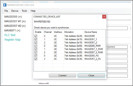
Figure 2. MAX20355 + MAX20357 Communication Window
Note that MAX20357 is in the SYSULVO mode if it is initially powered-up from the BAT pin. There is no I2C access to the MAX20357 in the SYSULVO mode. A valid PLC voltage is required to wake up the MAX20357 and enable I2C access. Recommend installing J40/J41 during start-up to activate MAX20357 after POR.
GUI Software Layout
Status, interrupt, and user configuration of the integrated PLC and charging system are distributed under various sections in the menu located on the left of the window, as shown in Figure 3.
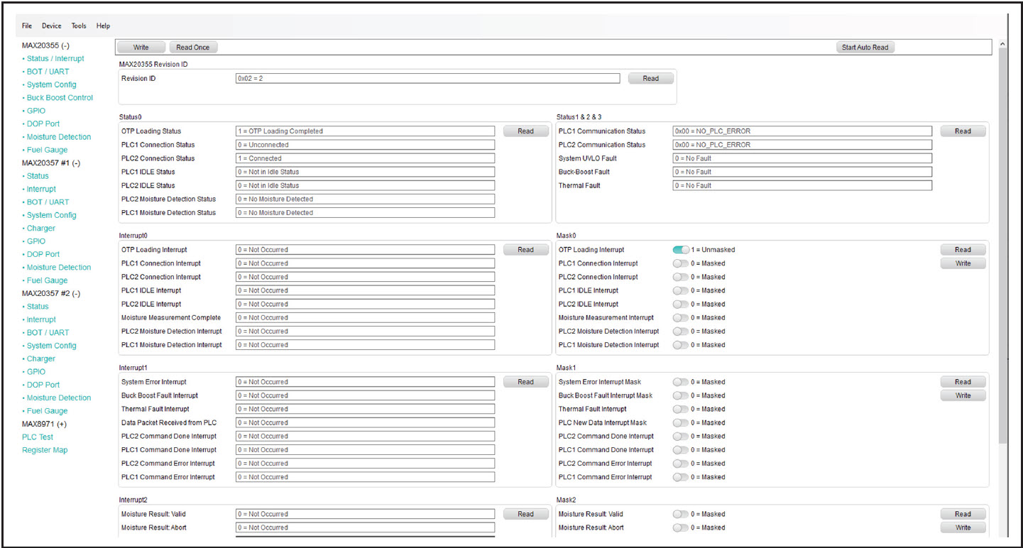
Figure 3. MAXREFDES182 GUI with Fully Expanded Submenus
MAX20357 #1, and MAX20357 #2 sections monitor status, interrupt, and important fuel gauge information in the DOP Port, and customize the behavior of the PLC interface, integrated buck-boost, charger, SYS LDO, power path, GPIO, UART, and moisture detection.
PLC Test section evaluates various PLC commands. Access MAX20355, MAX20357 #1, and MAX20357 #2 RAMs in this section for mailbox data transfer verification. Note that bulk data transfer is not supported on the GUI software.
Register Map section allows to view the register map of the following devices and write to register bit: charger IC MAX8971, PLC Master IC MAX20355, Master fuel gauge, two PLC Slave ICs MAX20357_1 and MAX20357_2, Slave fuel gauges, and RAMs of all the PLC devices. Click the register field to get the register name, field name, and decode chart of each register field. Figure 4 shows an example of register information.
![Register Map, MAX20357_1, ChgStat (0x02[3:0])](/en/_/media/analog/en/reference-design-maxim-images/maxrefdes182/maxrefdes182-fig4.jpg?rev=8f8bc0959f70488e8a0ce6e3960a1fc7&sc_lang=en)
Figure 4. Register Map, MAX20357_1, ChgStat (0x02[3:0])
Selecting the MAX20355
Major function blocks of the MAX20355 are distributed under various submenus in the MAX20355 section. Click the appropriate tab to move to the desired registers.
- Status / Interrupt displays status and interrupt.
- BOT / UART displays device power states control, fuel gauge on/off control, and UART-related registers.
- System Config displays configurations of the PLC interface, information of received data packet, and FIFO status during bulk transfer.
- Buck Boost Control displays the integrated buck-boost converter-related registers, including automatic voltage adjustment algorithm, default charging voltage, communication voltage, etc.
- GPIO displays the general purpose inputs/outputs (GPIO) configuration of MAX20355 and GPIO status of both MAX20355 and MAX20357.
- DOP Port displays important information of the charging case battery reported by the integrated ModelGauge m5 EZ, the cell voltage, state of charge, and charge done status of the two earbud batteries.
- Moisture Detection displays moisture detection-related registers.
- Fuel Gauge displays fuel gauge information from integrated ModelGauge m5 EZ. It contains five tabs: ModelGauge m5, Graphs, Registers, Configure, and Information. Use these tabs to read the real-time battery information, upload battery profile, and access all registers of ModelGauge m5 EZ.
Note that the GUI only logs data from integrated ModelGauge m5 EZ while Fuel Gauge section is open. Stay in the Fuel Gauge section if continuous I2C reading from ModelGauge m5 EZ is needed.
MAX20357 #1 and MAX20357 #2 Section
Major function blocks of the MAX20357 are distributed under various submenus in the MAX20357 #1 and MAX20357 #2 sections. Click the appropriate tab to move to the desired registers.
- Status displays status.
- Interrupt displays interrupt.
- BOT / UART displays power states control, reset request, fuel gauge on/off control, and UART-related registers.
- System Config displays configurations of the PLC interface, adaptive input current limit, power path, watchdog, and MAX20355 battery information.
- Charger Control displays the integrated charger-related registers, including charger operation, current, voltage, and JEITA-related settings,
- GPIO displays the GPIO configuration of MAX20357 and GPIO status of both MAX20355 and MAX20357.
- DOP Port displays important information of the earbud battery reported by the integrated ModelGauge m5 EZ.
- Moisture Detection displays moisture detection-related registers.
- Fuel Gauge displays fuel gauge information from integrated ModelGauge m5 EZ. It contains five tabs: ModelGauge m5, Graphs, Registers, Configure, and Information. Use these tabs to read the real-time battery information, upload battery profile, and access all registers of ModelGauge m5 EZ.
Note that the GUI only logs data from integrated ModelGauge m5 EZ while Fuel Gauge section is open. Stay in the Fuel Gauge section if continuous I2C readings from ModelGauge m5 EZ are needed.
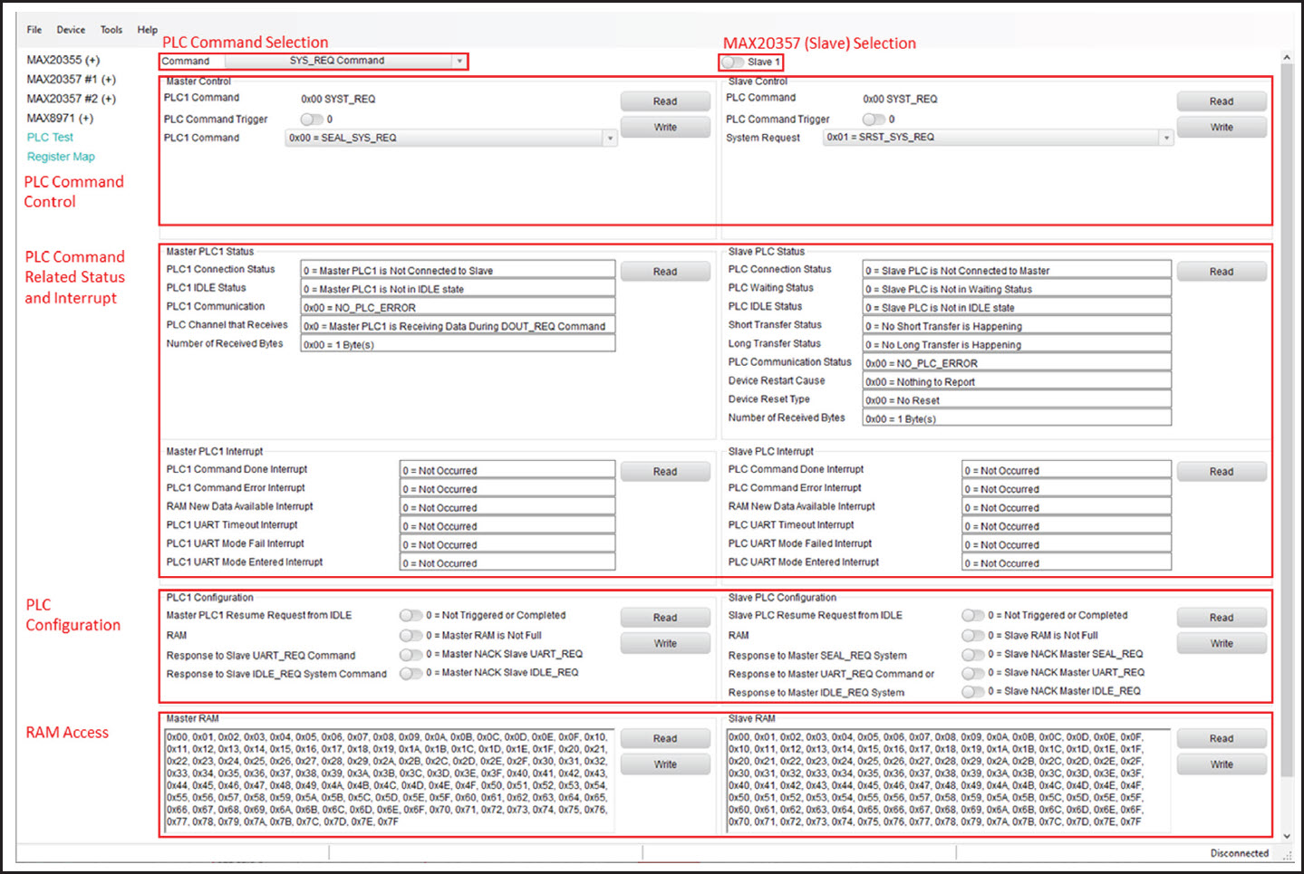
Figure 5. PLC Test Overview

Figure 6. PLC Test, Command and Slave Selection
MAX8971 Section
Major function blocks of the MAX8971 are distributed under various submenus in the MAX8971 section. Click the appropriate tab to move to the desired registers.
- Status/Interrupt displays status and interrupt.
- Charger Control displays all charger control registers including charge current, timer, JEITA, and protections.
PLC Test Section
The PLC Test section in Figure 7 evaluates various PLC commands of the system. Select the PLC command from the Command dropdown menu. Use the toggle button to select between Slave 1 (MAX02357_1) and Slave 2 (MAX20357_2) to receive or send PLC commands, as shown in Figure 8. The displays in the Master Control and Slave Control panels change accordingly when a different PLC command is selected.

Figure 7. MAX20355/57 PLC Test, MAX20355 Sends SET_GPIB Command to MAX20357_1

Figure 8. MAX20355/57 UART Connection
In the PLC Status and PLC Interrupt panels, PLC command-related status and interrupt are displayed to easily determine if a PLC command is sent and executed successfully. PLC configuration panel configures responses to certain PLC commands. RAM panel allows to access the integrated RAM.
PLC Command Status and Interrupt
For the IC that sends the PLC command, PLC Command Done Interrupt is generated after receiving a response (either ACK or NACK) to the PLC command. PLC Command Error Interrupt is generated if PLC command is finished with an error (for example, received a NACK packet). Check PLC Communication Status to determine the error type occurred during PLC command. If PLC Command Done Interrupt is generated and PLC Command Error Interrupt is not generated, PLC command is sent and acknowledged successfully.
SET_GPIO Command
Figure 9 shows an example of the MAX20355 sending the SET_GPIO command to the MAX20357_1.

Figure 9. MAX20355/20357 PLC Test, MAX20355 Sends UART_REQ Command to MAX20357_2
In the Master Control panel:
- Choose 'SET_GPIO' PLC command.
- Toggle PLC1 Command Trigger to '1'.
- Set GPIO configuration.
- Click Write. SET_GPIO command is sent at the next PING. PLC1 Command Trigger is auto-cleared to '0' after successfully sending the PLC command.
UART_REQ Command
In the UART mode, when the charging case transmits data to the earbud, data passes from the MAX20355 UART_T pin to the MAX20357 UART_TX pin. When the earbud transmits data to the charging case, data passes from the MAX20357 UART_RX pin to the MAX20355 UART_RX pin.
Master Sends UART_REQ Command to Slave
Figure 9 shows an example of the MAX20355 sending the UART_REQ command to the MAX20357_2.
In the Master Control panel:
- Choose 'UART_REQ' PLC command.
- Toggle Slave selection to 'Slave 2'.
- Toggle PLC2 Command Trigger to '1'.
- Set UART direction.
- Click Write. UART_REQ command is sent upon the next PING. PLC2 Command Trigger is auto-cleared to '0' after successfully sending the PLC command.
DOUT_REQ Command
On the GUI software, the DOUT_REQ Command is used to verify the mailbox data transfer. Figure 10 shows an example of the MAX20355 sending the DOUT_REQ command to the MAX20357_1.

Figure 10. MAX20355/20357 PLC Test, Master Sends DOUT_REQ Command to Slave1
In the Master Control panel:
- Choose 'UART_REQ' PLC command.
- Toggle Slave selection to 'Slave 2'.
- Toggle PLC2 Command Trigger to '1'.
- Select Number of Bytes to Transmit in this DOUT_REQ command. Up to 128-byte in one data packet.
- Click Write. DOUT_REQ command is sent upon the next PING. PLC2 Command Trigger is auto-cleared to '0' after successfully sending the PLC command.
As shown in Figure 11, after DOUT_REQ command is executed successfully, RAM in the PLC Configuration panel of the receiving device is set to 1. When RAM = 1, the PLC device sends NACK to the incoming DOUR_REQ command. Write RAM to 1 (click Write) to clear the flag. The device is ready to receive another data packet.

Figure 11. MAX20355/MAX20357 PLC Test, RAM
SYST_REQ Command
Figure 12 shows an example of the MAX20355 sending the SYS_REQ command to the MAX20357_1.
In the Master Control panel:
- Choose SYST_REQ command.
- Toggle PLC1 Command Trigger to '1'.
- Select system request type.
- Click Write. SYST_REQ command is sent upon the next PING. PLC1 Command Trigger is auto-cleared to '0' after successfully sending the PLC command.

Figure 12. MAX20355/20357 Master Sends SYST_REQ Command to Slave1
Table 5 lists the MAX20355 (Master)-initiated system requests. Table 6 lists the MAX20357 (Slave)-initiated system requests.
| PLC_ARG | System Request Type | Descriptions |
| 0x00 | SEAL request | Puts MAX20357 in SEAL mode |
| 0x01 | Soft reset request | Resets MAX20357 registers |
| 0x02 | Hard reset request | Cycle the power on MAX20357 SYS pin |
| 0x03 | Fuel gauge reset request | Resets registers of MAX20357 integrated fuel gauge |
| 0x04 | FIFO request | Locks PLC line for bulk data transfer from MAX20355 to MAX20357 |
| 0x05 | FREE request | Frees PLC line after MAX20355 completes bulk data transfer |
| 0x06 | IDLE mode request | Sends MAX20357 into IDLE mode. |
| 0x07 | Soft + Hard reset request | Resets MAX20357 registers and cycles the power on MAX20357 SYS pin |
| 0xFC | UBOOT request | Hard resets MAX20357 and puts MAX20355 and MAX20357 in UART mode. UART direction is configured manually through I2C. |
| 0xFD | UBOOT request | Hard resets MAX20357 and puts MAX20355 and MAX20357 in UART mode. UART direction: MAX20355 transmitting, MAX20357 receiving. MAX20357 UART_RX is connected to MAX20355 UART_R |
| 0xFE | UBOOT request | Hard resets MAX20357 and puts MAX20355 and MAX20357 in UART mode. UART direction: MAX20355 receiving, MAX20357 transmitting. MAX20357 UART_TX is connected to MAX20355 UART_T |
| 0xFF | UBOOT request | Hard resets MAX20357 and puts MAX20355 and MAX20357 in UART mode. UART direction: Local loop-back All UART pins are connected: MAX20357 UART_TX, UART_RX, MAX20355 UART_T, UART_R. |
| PLC_ARG | System Request Type | Description |
| 0x01 | Soft reset request | Resets MAX20355 registers |
| 0x03 | Fuel gauge reset request | Resets registers of MAX20355 integrated fuel gauge |
| 0x04 | FIFO request | Locks PLC line for bulk data transfer from MAX20357 to MAX20355. |
| 0x05 | FREE request | Frees PLC line after MAX20357 completes bulk data transfer |
| 0x06 | IDLE mode request | Sends MAX20355 into IDLE mode |
Detailed Description of the Fuel Gauge GUI
MAX20355, MAX20357 #1 and MAX20357 #2 all contain as submenus. The following sections take the Fuel Gauge of MAX20355 as an example to show how it works.
Program Tabs
All functions of the program are divided under four tabs in the main program window. Click the appropriate tab to move to the desired function page. The primary user information measured and calculated by the IC is located on the ModelGauge m5 tab. The Graphs tab visually displays fuel gauge register changes over time. The Registers tab modifies common fuel gauge registers one at a time. The Configure tab allows for special operations such as initializing the fuel gauge logging and performing fuel gauge reset. All tabs are described in more detail in the following sections.
ModelGauge m5 Tab
The ModelGauge m5 tab displays the important output information read from the IC. Figure 13 shows the format of the ModelGauge m5 tab. Information is grouped by function and each is detailed separately.
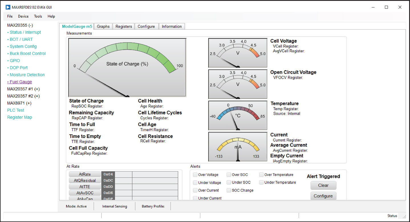
Figure 13. ModelGauge m5 Tab
State of Charge
The State-of-Charge group box displays the main output information from the fuel gauge: state-of-charge of the cell, remaining capacity, time-to-full, and time-to-empty.
Cell Information
The Cell Information group box displays information related to the health of the cell such as the cell's age, internal resistance, present capacity, number of equivalent full cycles, and change in capacity from when it was new.
Measurements
The Measurements group box displays ADC measurements used by the fuel gauge to determine state-of-charge.
Alerts
The Alerts group box tracks all eleven possible alert trigger conditions. If any alert occurs, the corresponding checkbox is checked for the user to see. The clear alerts button resets all alert flags.
At Rate
The At Rate group box allows to input a hypothetical load current and the fuel gauge calculates the corresponding hypothetical Qresidual, TTE, AvSOC, and AvCap values.
Graphs Tab
Figure 14 shows the format of the Graphs Tab. Graph information is grouped into four categories: voltages, temperatures, capacities, and currents. Turn on or off any data series using the check boxes on the right-hand side of the tab. The graph visible viewing area can be adjusted from 10 minutes up to one week. The graphs remember up to one week worth of data. If the viewing area is smaller than the time range of the data already collected, the scroll bar below the graphs can be used to scroll through the graph history. All graph history information is maintained by the program. Graph settings can be changed at any time without losing data.
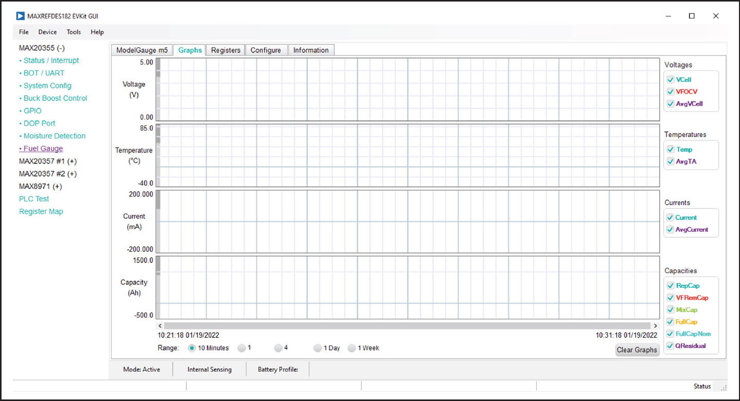
Figure 14. Graphs Tab
Registers Tab
The Registers tab allows access to all fuel gauge-related registers of the IC. Figure 15 shows the format of the Registers tab. Sort the registers either by function or by their internal address using the dropdown menu on the left side of the tab. Each line of data contains the register name, register address, hexadecimal representation of the data stored in the register, and, if applicable, a conversion to application units. To write a register location, click the button containing the register name. A pop-up window allows to enter a new value in either hexadecimal or application units. The main read loop temporarily pauses while the register updates.
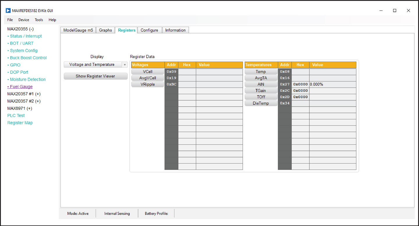
Figure 15. Registers Tab
Configure Tab
The Configure tab allows to access any general IC functions not related to normal writing and reading of register locations. Figure 16 shows the format of the Configure tab. Each group box of the Configure tab is described in detail in the following sections.
Read/Write Register
Read a single register location by entering the address in hexadecimal and clicking Read. Write a single register location by entering the address and data in hexadecimal and clicking Write. The read loop is temporarily paused each time to complete this action.
Log Data to File
Data logging is always active when the kit software starts. The default data log storage location is the Documents\Maxim Integrated\MAX20355_57\20355\Datalogs\Datalog.csv. Stop data logging by clicking Stop. Resume logging by clicking Start. All user available IC registers log in a .csv formatted file. Adjust the logging interval at any time. Also enable or disable the event logging at any time. When event logging is enabled, the data log also stores any IC write or reads not part of the normal read data loop and indicates any time communication to the IC is lost. The GUI automatically begins writing to a new file on each launch. To manually begin logging to a new file, click Advance.
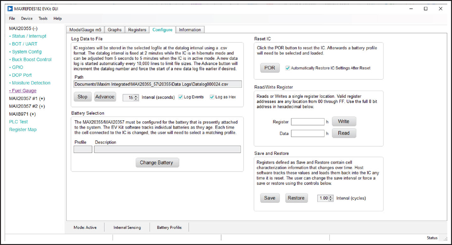
Figure 16. Configure Tab
Reset IC
Clicking the POR button sends the software POR command to the command register to fully reset operation the same as if the IC is power cycled. Note that resetting the IC when the cell is not relaxed causes fuel gauge error.
Selecting the Battery
Clicking Change Battery opens the battery selector window, where a battery profile is created. The battery profile stores the EZ Config model or custom INI for that battery, as well as any learned parameters, if the save and restore function is used. Ideally, a new profile is created for each battery to store these parameters. The software automatically programs the IC upon pressing Save Profile and Update IC.
Save and Restore
The EV Kit software periodically saves the values from the registers related to cell characteristics that change over time. These values are then restored into an IC after reset so that the fuel gauge remains accurate as the cell ages. The software automatically performs a save operation every 10 cycles or when the software exits. Change the save interval or force a save operation at any time by clicking Force Save. To restore this information after the IC is power cycled or reset through software, click Restore.
ModelGauge m5 EZ Configuration
Before the IC accurately fuel gauges the battery pack, configure it with characterization information. This can be accomplished in two ways. The first is through a custom characterization procedure performed by Analog Devices under certain conditions. The result is an .INI summary file that contains information that can be programmed into the IC on the Configure tab. Contact Analog Devices for details on this procedure.
The second method is ModelGauge m5 EZ configuration. This is the default characterization information shipped inside every IC. This default model produces accurate results for most applications under most operating conditions. It is the recommended method for new designs as it bypasses the custom cell characterization procedure. Some additional information is required from the user for EZ configuration initialization.
For EZ configuration, click Import INI File in the Information tab, or click Change Battery in the Configure tab. A Battery Selector panel, as shown in Figure 17, pops out. In the panel, select Use Default IC Settings (EZ Config). Fill in the rated battery capacity and the charge termination current, select the battery chemistry in the Model ID dropdown menu, and select the minimum system voltage in the Empty Voltage dropdown menu. Check the Charge voltage is greater than 4.275V box if the full charge voltage is higher than 4.275V. After configuring these items, click Save Profile and Update IC to load EZ configuration into the chip.
For characterized battery, choose Load INI File in the Battery Selector panel, and select the INI file provided by Analog Devices, then click Save Profile and Update IC to load the configuration.
Script Automation
Python-based script system is embedded in the GUI software to allow automating or configuring multiple registers sequentially with ease. To evaluate through Python-based commands, click Tools > Run Script File. A Script window pops up, as shown in Figure 17. The first tab consists of a script editor and an embedded Python Terminal Interface. The second tab provides the Python I/O console. The help tab provides a coding tutorial for this script window. Also use the dropdown list on the right side to choose Example 1 for an example script. Click Run to execute the script. The script feature helps with testing out a sequence of the configuration automatically.
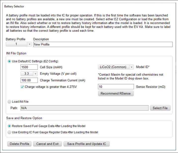
Figure 17. New Battery Selector Panel
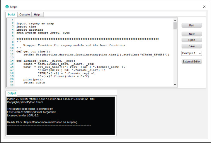
Figure 18. MAXREFDES182 Script Window
Documentation & Resources
-
MAXREFDES182 Design Files10/21/2022ZIP1 M
Support & Training
Search our knowledge base for answers to your technical questions. Our dedicated team of Applications Engineers are also available to answer your technical questions.

