
MAXREFDES1264


Overview
Design Resources
Description
The MAXREFDES1264 is a reference design for the MAX32630FTHR and MAX7404. It produces an accurate variable frequency sine wave for use as a general-purpose reference signal. The MAX7404 is an eighth-order elliptic switched-capacitor lowpass filter. The MAX32630FTHR is an ARM core-based low-power microcontroller board used to provide the clock and input signal to the MAX7400.
Parts Used
Details Section
TThe MAXREFDES1264 is a reference design for the MAX32630FTHR and MAX7404. It produces an accurate variable frequency sine wave for use as a general-purpose reference signal. The MAX7404 is an eighth-order elliptic switched-capacitor lowpass filter. The MAX32630FTHR is an ARM core-based low-power microcontroller board used to provide the clock and input signal to the MAX7400.
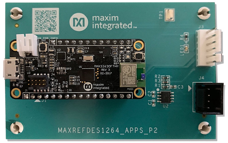
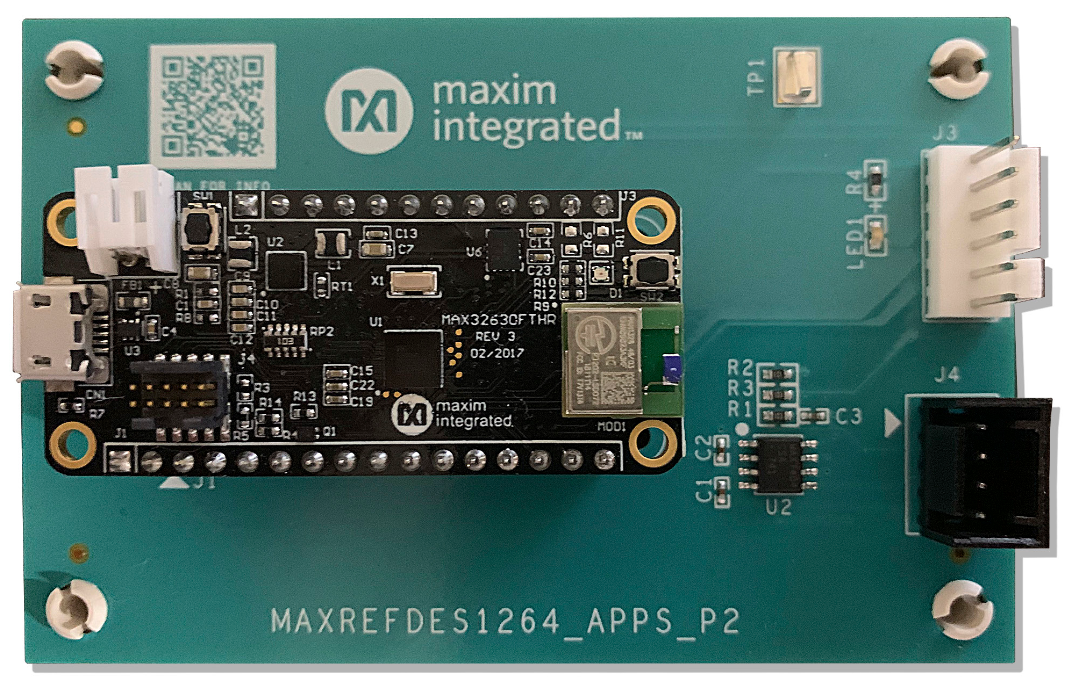
This document describes the hardware in Figure 1. It is a detailed, systematic technical guide to use a small, low-cost, portable sine-wave generator. The design was built and tested. The details follow later in this document.
| Parameter | Symbol | Min | Max |
| Input Frequency | VIN | 0Hz | 5kHz |
| Clock Frequency | CLK_IN | 0Hz | 500kHz |
- MAXREFDES1264
- A laptop or PC
A sine wave with an arbitrary frequency is needed as a reference signal during various designs and testing. A simple sine wave is generated by passing a square wave through a lowpass filter. The MAX7404 is the lowpass filter used in this design. It is an eighth-order elliptic switch-capacitor filter that converts the input square wave to a sine wave (Figure 2).
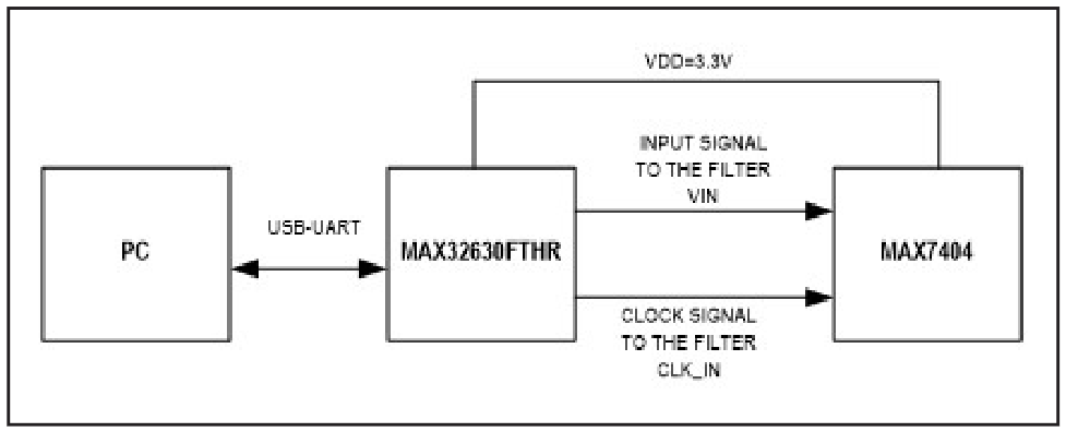
The microcontroller acts as a square-wave generator feeding the filter with both clock and input signals. The filter's cut-off frequency is 1/100 of the clock frequency. The user can modify the frequencies through a serial monitor program from the PC. The algorithm works as follows:
The microcontroller clocks the filter with a 100kHz square wave. The input frequency of the filter is 1kHz. The eighth-order elliptic filter's sharp roll off sharply reduces the harmonic amplitudes in a 1kHz square-wave input, thereby producing a near-perfect 1kHz sine wave at its output. A digitally adjustable sine-wave source can be created by adjusting the clock and input frequencies, and while maintaining a ratio of 100:1 between them (using the divider-chain logic or a processor). Figures 3, 4, and 5 show the clock, input, and output signals, respectively.
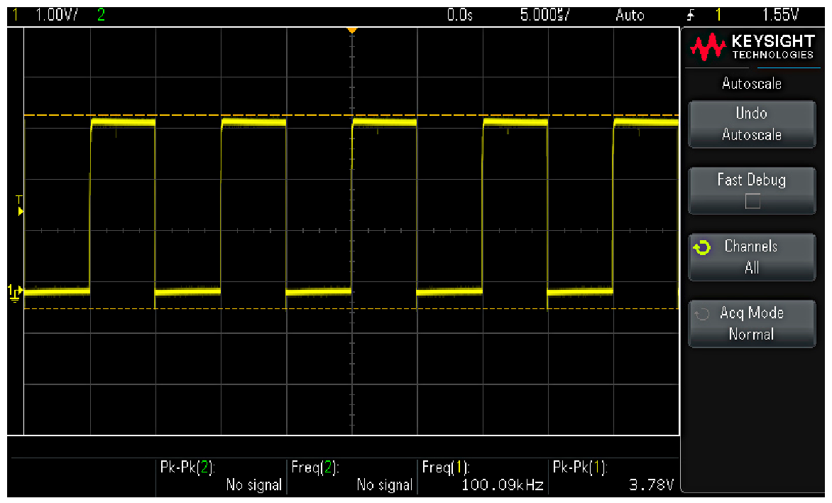
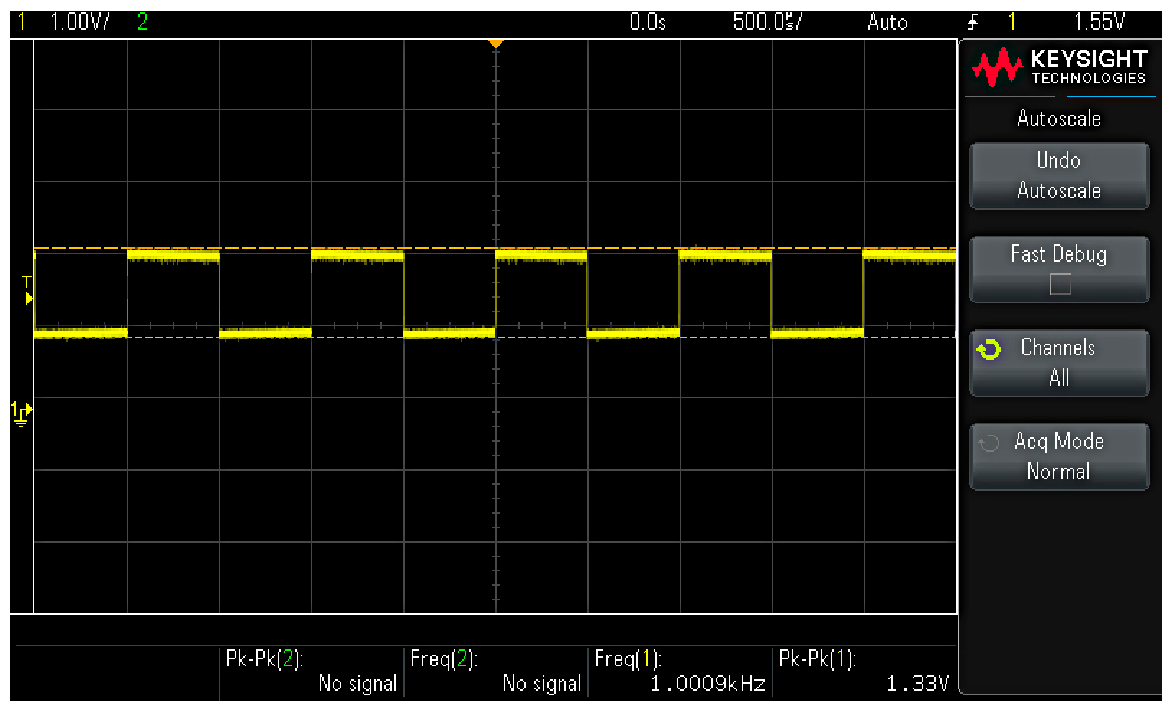
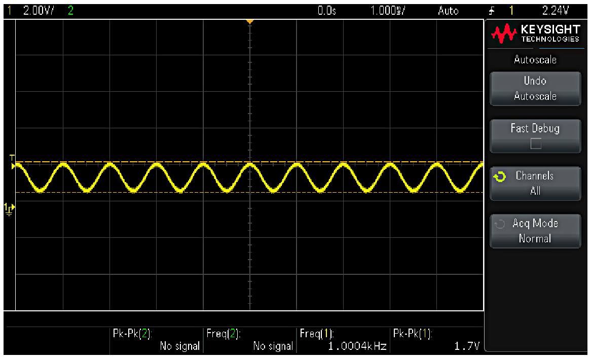
The firmware is developed using an online MBED compiler. The input frequencies can be varied using a serial application like the tera term using the Universal Serial Bus-Universal Asynchronous Receiver/Transmitter (USB-UART) protocol. The microcontroller feeds the filter with the square waves. The firmware is tested. It can be downloaded from the design resources tab. The filter has a cut-off frequency of 10kHz, which needs a clock signal of 1MHz. The firmware is designed to support an input signal range from 0 to 5kHz due to the limitations of the MBED compiler to generate a 1MHz clock signal.
Documentation & Resources
Support & Training
Search our knowledge base for answers to your technical questions. Our dedicated team of Applications Engineers are also available to answer your technical questions.