


Overview
Features and Benefits
- Fully featured evaluation board for the ADP5140
- Compact solution size
- 4-layer, high glass transition temperature (TG) PCB for superior thermal performance
- Connections through vertical, printed circuit, tail pin headers
- Supply voltage: 3.5 V to 4.1 V (3.7 V typical)
- Adjustable output for Buck2 and Buck3 regulators
- Fixed output for Buck1, Buck4, boost, and all LDO regulators
- Fixed start-up sequence
- Voltage monitor and watchdog function
- RESET, FAULT, and STATUS outputs
- SPI communication protocol
Product Details
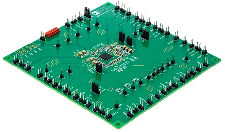
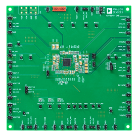
The ADP5140-EVALZ provides a complete and compact solution that allows users to evaluate the performance of the ADP5140 with a near ideal printed circuit board (PCB) layout.
The main device on the ADP5140-EVALZ, the ADP5140, integrates four high performance, synchronous step-down buck regulators (Buck1 to Buck4), one boost regulator, and seven low noise low dropout (LDO) regulators (LDO1 to LDO7). Each voltage rail is monitored internally and any fault event is reported to the system through the RESET pin, FAULT pin, and STATUS pin.
The ADP5140-EVALZ has enable and sequence controls for all regulators that allow every voltage rail to start up with a fixed sequence.
The ADP5140-EVALZ has a serial peripheral interface (SPI) for system control and diagnostics. A dedicated graphical user interface (GUI) software is associated with the ADP5140-EVALZ for flexible evaluation of the ADP5140.
For full details on the ADP5140, see the ADP5140 data sheet, which must be consulted in conjunction with the user guide when using the ADP5140-EVALZ.
Applicable Parts
Package Contents
- ADP5140-EVALZ
- USB-SDP-CABLEZ serial interface cable
- ADP5140 GUI software
Getting Started
DOCUMENT NEEDED
- ADP5140 data sheet
SOFTWARE NEEDED
- ADP5140 GUI software
EQUIPMENT NEEDED
- DC power supply
- Electronic load
- Oscilloscope