Overview
Features and Benefits
For Rev B and Rev C/D please review schematics found below.More info can be found on the ADAR1000 Wiki page.
- Based on the ADAR1000 4-channel beamformer core chip
- Controllable through SPI
- Multiple forms of digital interface (3.3 V and 1.8 V logic)
- On-board logic level translators with 1.8 V low dropout regulator for supply
- Software control from a Windows-based PC through USB
Product Details
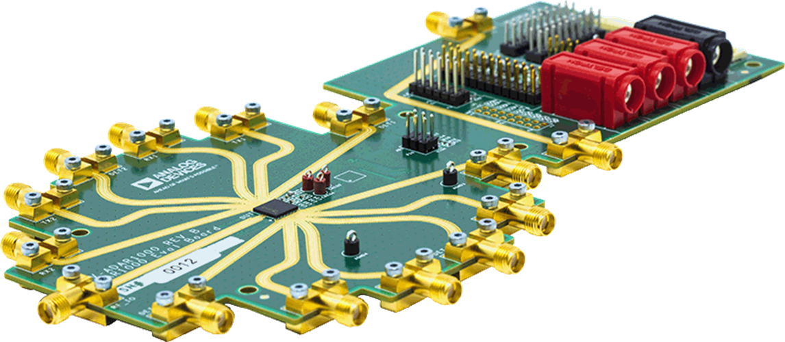
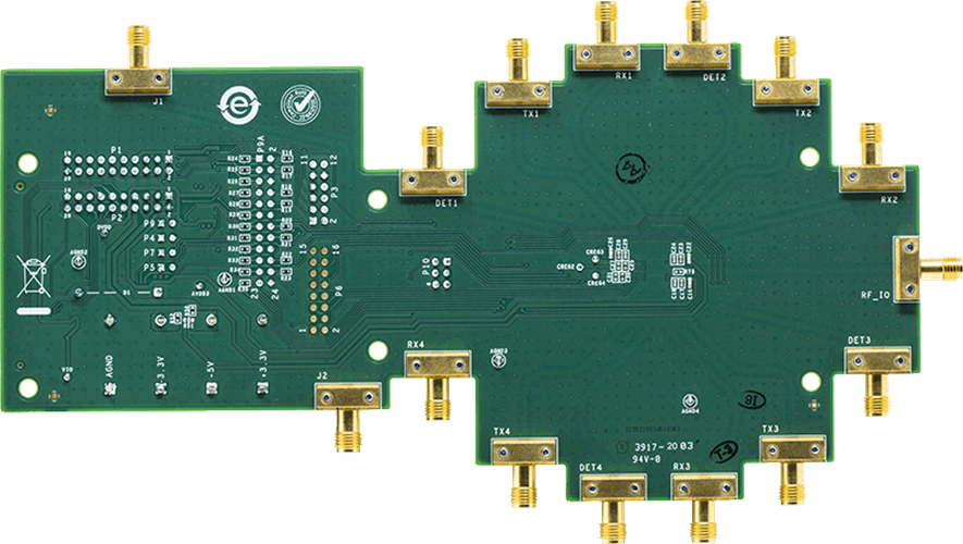
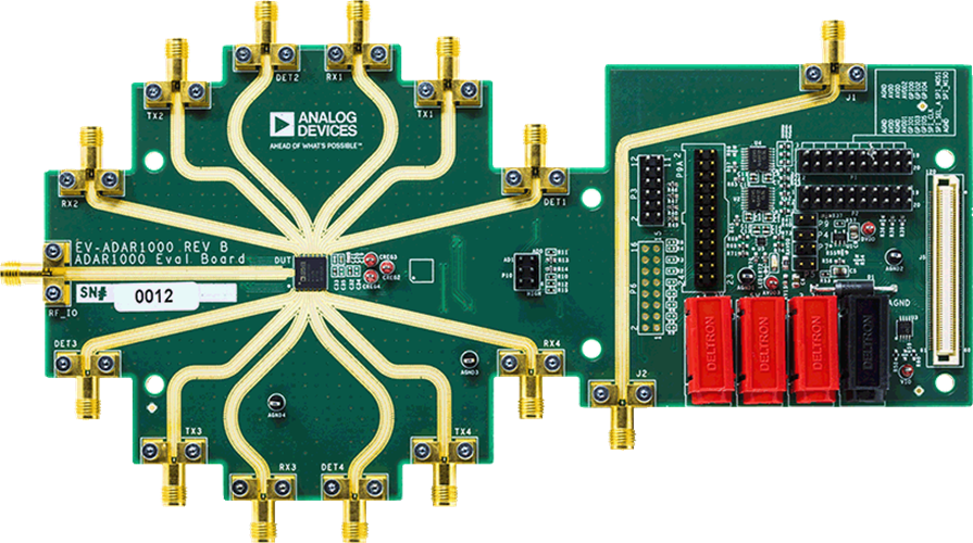
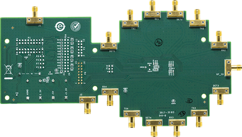
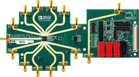
The ADAR1000-EVALZ evaluation board is designed for evaluating the performance of the ADAR1000, a 4-channel, X band and Ku band beamforming core chip for radar systems. All the radio frequency (RF) input/output channels and detector inputs are brought out to Subminiature Version A (SMA) connectors. On-board logic level translators convert the on-chip 1.8 V logic signals to 3.3 V for interfacing to external controllers running on 3.3 V. Two identical 20-pin, dual row rectangular headers provide the digital interface signals to allow daisy-chaining up to four ADAR1000-EVALZ evaluation boards together. A 24-pin connector provides control and bias outputs to interface to four external transmit and receive (T/R) modules with each ADAR1000-EVALZ evaluation board.
The ADAR1000-EVALZ evaluation board can be used with an Analog Devices, Inc., system demonstration platform (SDP) SDP-S or SDP-B board (supplied separately), which allows connection to a Microsoft Windows®-based PC through the USB for controlling of all the ADAR1000 device functions.
For full details on the ADAR1000, see the ADAR1000 data sheet, which should be consulted in conjunction with this user guide when using this evaluation board.
Markets and Technologies
Applicable Parts
Documentation & Resources
-
ADAR1000 Memory Map3/6/2021PDF8 M
-
ADAR1000 - Schematic (Rev. E)7/8/2020PDF446 K
-
ADAR1000 - Schematic (Rev. C/D)7/8/2020PDF430 K
-
ADAR1000 - Schematics (Rev. B)6/17/2020PDF50 K
-
ADAR1000 Gerber Files (Rev. E)3/3/2025ZIP1 M
-
ADAR1000 Max Gain Settings5/7/2021ZIP1K
-
ADAR1000 Gerber Files (Rev. C/D)7/8/2020ZIP1 M
-
ADAR1000 Gerber Files (Rev. B)6/8/2018ZIP697 K
