LNA for MMDS Band (2.65GHz) Features Gain Step
Abstract
The MAX2645 is a Silicon Germanium (SiGe) Low-Noise Amplifier (LNA) that features a 25dB gain step, shutdown mode, and adjustable IP3. The LNA has been optimized for wireless broadband applications in the MMDS, 2.65GHz frequency range. The MAX2645 features +17.5dB of gain, noise figure of 2.0dB, and an IIP3 of +3.7dBm in the high gain mode. In low gain mode, the MAX2645 provides 7.9dB of insertion loss and an IIP3 of +15.8dBm. With a typical operating supply voltage of +3.3V, the supply current is a low 8.9mA in the high gain mode, 2.7mA in the low gain mode, and typically 0.1µA in the shutdown mode.
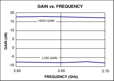
Table 1 summarizes the performance of the MAX2645 operating at 2.65GHz. The schematic used to optimize the MAX2645 for 2.65GHz is represented in Figure 1. Table 2 is the component list. Figures 2 through 6 demonstrate the performance of the LNA in both high gain and low gain modes over the frequency band of 2.6GHz to 2.7GHz. Tuning capacitors are common Murata 0402 GRP1555C (GRM36) series, and the tuning inductors are Murata 0402 printed LQP10A series. For further information, consult the MAX2645 SiGe LNA datasheet and EV kit datasheet.
| Mode | ICC (mA) | Gain (dB) | NF (dB) | IIP3 (dBm) | S11 (dB) | S22 (dB) |
| High Gain | 8.9 | +17.5 | 2.0 | +3.7 | 10.5 | 19.4 |
| Low Gain | 2.7 | -7.9 | 14.2 | +15.8 | 8.4 | 8.2 |
| Note: VCC = +3.3V, RBIAS = 20kΩ | ||||||

Figure 1. MAX2645 SiGe LNA performance at 2.65GHz.
| Designation | Quantity | Description |
| C1 | 1 | 2.0pF ±5% ceramic capacitor (0402) Murata GRM36C0G020C50 |
| C2 | 1 | 47pF ±5% ceramic capacitor (0402) Murata GRM36C0G470J50 |
| C3 | 1 | 10µF, 16V tantalum capacitor AVX TAJC106K016 |
| C4, C5 | 2 | 0.1µF ±10% ceramic capacitors (0603) Murata GRM39X7R104K016 |
| C6 | 1 | 33pF ±5% ceramic capacitor (0402) Murata GRM36C0G330J50 |
| C7 | 1 | 10pF ±5% ceramic capacitor (0402) Murata GRM36C0G100D50 |
| L1 | 1 | 3nH ±5% inductor (0402) Murata LQG15HN3N0S02 |
| L2 | 1 | 6.8nH ±5% inductor (0402) Murata LQG15HN6N8J02 |
| L3 | 1 | 5.6nH ±5% inductor (0402) Murata LQG15HN5N6S02 |
| R1 | 1 | 20kΩ ±1% resistor (0603) |

Figure 2. MAX2645 gain vs. frequency plot.

Figure 3. MAX2645 noise figure vs. frequency plot.

Figure 4. MAX2645 input IP3 vs. frequency plot.

Figure 5. MAX2645 input return loss vs. frequency plot.

Figure 6. MAX2645 output return loss vs. frequency plot.