Design Note 210: 2-Phase, Dual Switching Regulator Fits in Tight Places
Almost every week manufacturers present yet another component that has been reduced in size by 30% to 50% while maintaining similar performance characteristics. The size and weight requirements of the notebook and sub-notebook computer market has resulted in the development of increasingly smaller components. These consumer products have placed very stringent requirements on size, weight and run time. Because of component density, heat dissipation has also become one of the highest concerns for notebook computers and other portable equipment.
The third generation switching regulator controllers from Linear Technology address these new requirements. The LTC1628, a 2-phase, constant frequency, dual synchronous buck controller, has been specifically designed to minimize both the size and total cost of the power system while delivering the highest efficiency in the industry.
A 2-phase switching technique minimizes the peak and resultant RMS input current while doubling the effective frequency of the input current pulses. The input capacitor ESR requirement is reduced by 40% and the capacitance requirement is reduced by 75% when compared to a single phase controller solution! Ceramic input capacitors provide an ideal choice for the resultant requirements. Figure 1 contrasts the power loss due to the input RMS ripple current for a single and 2-phase solution over the 5V to 25V input voltage range for a 5V/3A and 3.3V/3A power supply. The input path resistive losses include the ESR of the input capacitor, internal battery resistance, PC trace/connector losses, fuse resistance and diode or MOSFET resistance that may be used in the power path for switching power sources.

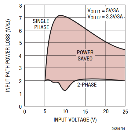
Figure 1. Input Path Power Loss.
The third generation controllers have also been designed to minimize the output capacitor requirements. External OPTI-LOOP® compensation allows optimal loop compensation for the wide range of characteristics associated with switching power supply output capacitors. A unique Burst Mode® architecture keeps the low current output voltage ripple down to a value close to the normal value for the continuous mode of operation, even when using output capacitors in the 47μF range. The output capacitor ESR requirement is determined by the expected load step and the capacitance value is determined by output current and speed of the feedback loop. A higher capacitance value cannot make up for high ESR and very low ESR cannot make up for insufficient capacitance.
A third key element in reducing solution size is an internal current foldback circuit that operates when the output voltage drops below 70% of the nominal value. This feature enables the use of MOSFETs properly sized for the output load current without additional power dissipation margin required for short-circuit conditions.
The application shown in Figure 2 occupies less than two square inches of PC board area (components on one side only) and delivers 5V/3A, 3.3V/4A, and 12V/150mA—the three main system power supplies for a notebook computer. The application in this Design Note addresses very common requirements of small physical size and dynamic 1A step load changes. Single, low ESR capacitors were used for the input and each output. Dual-packaged MOSFETs are used to further minimize PC board space. The inductors were selected based upon the maximum inductance for a reasonable case size while meeting peak current requirements. The photo in Figure 3 shows normal output ripple voltage and transient response to a 1.5A to 2.5A load step in continuous mode (5V output). The output ripple voltage is 25mVP-P and the 1A load steps result in 60mV output voltage transients. The output ripple voltage in Burst Mode operation is 70mVP-P. The efficiency of the power supply with a 15V input voltage and 5V/3A, 3.3V/3A and 12V/120mA output voltages measures 91%.

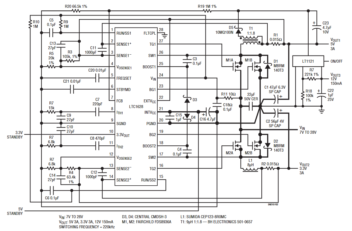
Figure 2. Two Square Inch 5V/3.3V/12V Portable Power Supply.

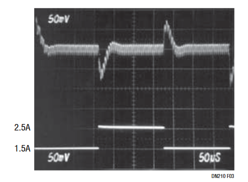
Figure 3. Upper Trace: 5V Output, Transient Load Response (50mV/DIV) Bottom Trace: Load Current (1A/DIV).
Other features of the LTC1628 include:
- A 0.8V reference and 1% output voltage accuracy over line, load and temperature variations
- 7.5% overvoltage “soft-latch”
- Defeatable overcurrent latch-off timer
- Adjustable soft-start
- 25μA shutdown current
- 5V and 3.3V standby linear voltage regulators
- Loop bandwidth normally limited only by external inductor, output capacitor, switching frequency and the quality of the printed circuit board design
Author
