MAX32570 Contactless PCD Application Note—EMV 3.0 Level 1 Analog
Abstract
The EMV® Contactless 3.0 specification recently introduced by EVMCo LLC significantly changed the requirements for compliant contactless payment solutions. This new version institutes many difficult requirements at the hardware level and multiplies the number of required analog test cases and design complexity by more than three times. This application note supplements existing antenna matching and analog front end (AFE) configuration and tuning guides, providing specific guidance to meet the new requirements and pass rigorous certification testing. It covers radio frequency (RF) power considerations, antenna design optimization, antenna matching, proximity coupling device (PCD)-to-proximity integrated circuit card (PICC) signal integrity issues, loading effects, PICC-to-PCD receiver performance, and specific EMV Level 1 testing requirements and cases.
Introduction
This application note provides focused guidance for EMV 3.0 compliance. It assumes readers are familiar with the content of PCD Antenna Matching Design Guide and the AFE Tuning Guide which are provided with the SDK for the MAX32570. These documents include the necessary building blocks for the techniques used in this application note. Due to the complexity of EMV 3.0, these documents may prove insufficient to meet all the new requirements of EMV3.0. Therefore, this application note provides supplementary guidance for EMV 3.0-compliant product development using MAX32570.
Identify Target Protocols
When a near field communication (NFC) product is designed with MAX32570, the system architect should identify the target standards and application scenarios that the product complies with. Major NFC standards include ISO14443A/B, ISO15693, ISO18092, FeliCa, NFC Forum, etc. This document specifically targets EMV PCD Contactless Specification v3.0 compliance, covering a subset of ISO14443A/B contactless standards. The system architect and designer should be aware that EMV 3.0 compliance does not guarantee compliance of any other standards although other standards overlap with EMV 3.0 specifications. The hardware level optimization process detailed in this document can be applied to other standards and scenarios. However, each target protocol should be considered and optimized individually before finally combing with EMV 3.0 support if the final product supports multiple protocols.
EMV 3.0 Complexity
The EMV 3.0 Contactless Specification was evolved from EMV 2.6 and is mandatory since 2019. The main changes of EMV 3.0 as compared to its EMV 2.6 counterpart are as follows:
- EMV 3.0 requires interoperability tests in addition to analog and digital tests.
- EMV 3.0 analog test requires testing with three EMVCo Reference PICCs (with different antenna sizes or different PICC resonant frequencies) whereas EMV 2.6 requires only one.
- Each EMVCo Reference PICC in EMV 3.0 analog test has two linear loads for PCD-to-PICC signal integrity/waveform test whereas EMV 2.6 EMVCo Reference PICC has only one linear load.
These changes clearly increase the complexity of the EMV compliance tests. The time required for the EMV 3.0 test execution is approximately 6 times longer than EMV 2.6. Depending on the lab and test equipment, the minimum time required to complete an analog test ranges from 2 to 5 days, assuming no issues. For that reason, it is crucial to follow certain debugging and optimization steps in order to reduce the time and cost of EMV-compliant product development. EMV 3.0 analog test cases are available at the EMVCo website.
PCD RF Power
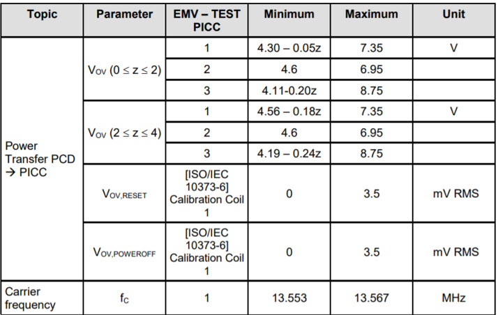
The RF power test cases TAB111.x.1.zrf (where x = 1, 2, 3 for different reference PICCs and zrf represents the position relative to the origin) are the first group of test cases a PCD design must pass. Each test case of TAB111 has a VMAX and VMIN to govern the allowed range of the DC voltage seen at the J1 port of a reference PICC, as shown in Table 1. This voltage indicates magnitude of PCD's generated magnetic field at the specified location. Typically, test positions of 0cm and 4cm for each PICC are the critical cases to meet the requirements of VMAX and VMIN, respectively. Once a PCD passes at 4cm and 0cm, it has a very low chance to fail any other TAB111 test case. Passing these tests primarily requires optimization of antenna matching network and electromagnetic compatibility (EMC) filter design.
Table 1. Power Transfer Requirement from PCD to PICCs
Antenna Design Optimization
In addition to the general guidance described in the PCD Antenna Matching Design Guide, this document is provided to optimize some important PCD antenna coil parameters to pass the EMV 3.0 RF power tests.
Antenna Size
The magnetic field distribution of a simple circular loop is shown in Figure 1. From the equation, if differentiating H(x,r) with respect to r , its first derivative equals zero when r = v2x, and this is a theoretical conclusion for the antenna size selection to maximize the power at a distance. For EMV RF Power specs, x is 4cm, therefore, the best reader coil diameter is 11.32cm to deliver the highest field at 4cm (EMV test cases TAB111.x.1.400) given the same amount of current.
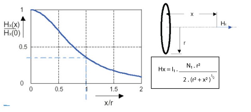
Figure 1. Magnetic field distribution of a simple circular loop, N1 is number of turns and I1 is current in the loop.
Figure 2 shows the magnetic field distribution of coils with different sizes under the same current (1A) and number of turns (N = 1). It clearly shows that under certain field restrictions (HMIN, HMAX) within an operating volume, there exists a minimum size that can possibly meet such restrictions. This is directly applicable for standards like ISO 14443, as its specs were defined in terms of the magnetic field. It can be inferred from both the curve in Figure 2 and the equation in Figure 1 that smaller coils always tend to have stronger variation over the same distance ranging from 0 to x. This is because the term H(x)/H(0) is monotonically decreasing as r increases, and when r goes to infinite H(x)/H(0) reaches its minimum, which is 1. However, EMV power test cases attempt to govern both HMAX and HMIN, and the challenge for a PCD is usually passing test cases TAB111.x.1.40x minimum and TAB111.x.1.000 maximum requirement at the same time. Since EMV originated from the ISO14443 standard, in this application note the upper limit of H(x)/H(0) is roughly estimated through HMIN/HMAX defined in ISO14443, which is (1.5A/m)/(7.5 A/m) = 0.2. So, the minimum can be derived through H(r, x)/H(r, 0) = 0.2, yielding r = 0.72x. This hypothetically gives the smallest possible circular coil diameter of 5.76cm to be able to satisfy ISO14443.
For NFC, a nonideal target causes field distribution change as well as loading effect that affect the source current going through the PCD antenna, and hence makes it possible to pass the EMV power test even with an antenna size smaller than 5.76cm. There are other challenges to pass all the EMV test cases with an antenna size below 6cm. Intelligent RF driver control techniques such as dynamic power control (DPC) can reduce the RF power variation.
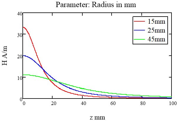
Figure 2. Impact of antenna size on magnetic field distribution.
For EMV 3.0 tests, due to the finite coil size of EMVCo reference PICCs, research on the mutual inductance of a PCD-PICC antenna pair is of more interest than just looking at the field without a PICC target. Figure 3 depicts the mutual inductance of a two-coil system. If the radius of coil1 (r1) is fixed, for a certain distance, there exists an optimum radius of coil2 to reach the maximum mutual inductance. Considering a fixed size reference PICC, there exists an optimum PCD size to optimize the mutual inductance of the system at 4cm (the longest distance defined in EMV 3.0 operating volume). The reference PICCs are of rectangular shape, therefore the calculation is more complicated. However, it can still be roughly estimated that the optimal PCD size that maximizes the mutual inductance at 4cm with reference to PICC1 or PICC2 antenna (around 8cm by 4cm) would be around 12cm by 8cm. The optimal PCD size that maximizes the mutual inductance at 4cm with reference to PICC3 antenna (around 4.5cm by 3.5cm) would be around 9cm by 7cm. Therefore, antenna around 10cm by 8cm would be a practically optimal size for EMV 3.0. However, for the modern compact PCD product designs which have less available area, it is common to just define the antenna size by utilizing as much area as the physical device allows.
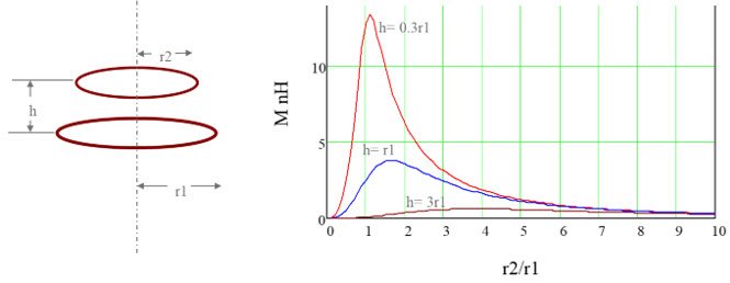
Figure 3. Mutual Inductance of a two-coil system.
Number of Turns
Once the antenna size is determined, another design variable affecting the RF power is the number of turns of the PCD antenna. The inductance of a PCD coil has a second order dependence on its number of turns, while the mutual inductance of a PCD-PICC pair has a first order dependence on the number of turns of the PCD antenna. Therefore, increasing the number of turns normally increases the RF power for EVMCo test. However, even though the mutual inductance can always be boosted by increasing the number of turns, the current that feeds into the antenna drops at the same time since:
- Any NFC transmitter, including that in MAX32570, can never be an ideal constant current source.
- The resistive loss of the PCD coil cannot be ignored and it significantly increases as the number of turns increases.
For that reason, and the requirement of maximum RF power, there exists an optimal number of turns to best satisfy the overall RF power specifications of the EMV 3.0, and such optimal number decreases as the given size increases. For example, assuming a PCD antenna with a size 7cm by 5cm is practically matched to MAX32570 and the optimal number of turns is usually 3 or 4 depending on other antenna parameters like materials and close-by metallic objects. Typically, a reasonable number of turns results in a self-inductance of the coil in the range of 0.5–3µH.
Other Antenna Parameters
Other antenna parameters including the substrate materials and coil trace width impact the RF power performance. For example, wider traces reduce the power loss of the antenna but slightly decrease the inductance, and hence the mutual inductance when associated with a PICC target. Material wise, it is straightforward to pick up the higher conductivity material for the metal layer and lower dielectric loss material for the substrate whenever possible. It is now becoming popular to use copper wires for the NFC antenna instead of printed circuit board because it does not suffer from substrate loss and the modern manufacturing technology can mass produce copper wire coils with good enough precision and low enough cost to beat its PCB counterpart. Also, it is more convenient for the prototyping phase to optimize the antenna geometrical parameters, which reduces the design time and cost.
External Components in Proximity
In modern compact NFC reader designs, having metal structures in the proximity of the antenna is sometimes unavoidable, for example, touch screen, keypad, contact IC card reader etc. When magnetic fields feed through a metallic surface, eddy currents are induced within the metal which are in the opposite direction of the original current. This effectively reduces the overall magnetic field in the operating volume. There are three common approaches to address this issue:
- Change the physical design and adjust the distances and/or angles of the metallic objects in the proximity.
- Place the permeable shielding material such as ferrite sheets between the antenna and the metal surface. This prevents eddy currents to a certain extent depending on the thickness, area, and placement of the ferrite.
- Design an antenna with higher power margin at stand-alone condition to compensate the power degradation when combined with the metallic objects in proximity.
The product designer must carefully consider the tradeoffs among RF performance, BOM cost, and product physical design restriction to decide which approach to choose.
Antenna Matching Condition Optimization
Once the antenna is defined, the matching network design is critical to deliver adequate current and minimize the reflection of the RF power. A detailed guidance for the antenna matching with MAX32570 is already described in the PCD Antenna Matching Design Guide. The additional design considerations are provided in the following sections to further improve the RF power performance.
Selection of Matching Point
There exists an optimal Rmatch to deliver the highest RF power to the PICC. It is noted that this optimal point is higher than the optimal Rmatch which delivers the highest power to the overall network after the Tx driver (which is equal to the effective TXP to TXN output impedance according to conjugate matching theory). This is due to the loss in the antenna, components of the network, as well as the trace loss on the path. The higher the overall loss, the larger the optimal Rmatch is. It is recommended to select Rmatch slightly higher than the optimal point due to the following three reasons:
- Higher Rmatch reduces the heat produced inside the MAX32570 IC, eliminating the need for additional thermal design considerations.
- Higher Rmatch increases power efficiency significantly, thereby increasing the battery life.
- Increasing Rmatch from the optimal power point only slightly decreases the RF power, therefore setting Rmatch higher than the exact optimal matching point is preferred.
It is with reference to these reasons that the PCD designer should consider the tradeoffs between heat, energy efficiency, and the RF power. For MAX32570, a matching point from 5Ω to 12Ω is the practical range depending on the antenna design and overall losses in the matching circuitry.
EMC Filter Optimization
General design guidance of EMC filter is described in the PCD Antenna Matching Design Guide. To further boost RF power, increasing the filter cutoff frequency up to 26MHz helps. The tradeoff is more challenges in the EMC compliance and in the EMV signal integrity tests that are detailed in the next section. The EMC inductor typically is the major contributor in the overall loss of the PCD circuitry, therefore higher Q inductors boost the current and hence the RF power. Alternatively, smaller inductance values and with the same Q on the inductor also help lower the resistive loss.
During the layout design, the overall trace length on the PCB for the matching network is recommended to be as short as possible. The distance between transmitter output and EMC filter is the most critical. This is due to the presence of harmonics of the 13.56MHz carrier on the transmitter outputs of the MAX32570, driven as square waves. Long traces increase the likelihood of capacitive and inductive coupling on neighboring circuits, which can lead to disqualifying spurious radiation and conduction levels in EMC tests. For general recommendations for layout of RF circuits, refer to Tutorial 4636.
Figure 4 illustrates an example layout of the EMC circuit. The transmitter outputs from the MAX32570 enter from the right and the antenna connections are on the left.
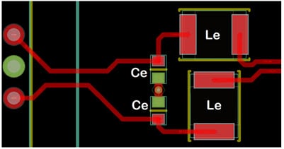
Figure 4. An example layout of EMC circuit.
As Figure 4 shows, the Le inductors are aligned perpendicular to each other as recommended in Maxim Tutorial 4636 to reduce coupling between them. However, these inductors can couple high harmonic signal content onto other circuits so shielded inductors are recommended for these components if the design can afford the lower quality factors (Q) in these inductors that result from inductor core losses. Unshielded inductors can be used if physical isolation from neighboring circuits is sufficient, especially if a higher circuit quality factor is needed.
Loading Effect from the PICC
The mutual inductance of PCD-PICC system also changes the effective impedance of the PCD antenna especially when PICC is close to the PCD. The matching condition is also affected; for normal unsymmetrical matching, the matching point shifts to higher impedance therefore it helps lower the RF power at shorter distance. That is one of the reasons why the theoretical size limitation derived from Figures 1 and 2 can be broken through.
A very important benefit of the loading effect from PICC is that it provides a variation sensible by the field detection (FD) circuit at receiver. As described in the AFE Tuning Guide, this can be utilized as feedback to determine the PICC position so the PCD can dynamically adjust its settings to read cards and pass EMV test cases at different positions and load conditions.
It is worth mentioning that dynamic power control through FD level can further minimize the variation of the RF power delivery to PICC across a range of distances. For unsymmetrical matching, it requires a complicated firmware algorithm, while for symmetrical matching a simple negative feedback decision algorithm can serve the purpose. The loading effect is mainly determined by PCD and PICC antennas, but EMC filter cutoff frequency also affects the loading effect direction and strength. Usually a lower cutoff frequency reduces the shift of matching point toward higher impedance. Once the cutoff frequency approaches 14MHz, it starts reversing the direction and becomes a symmetrical matching. It is recommended to design the PCD with unsymmetrical matching with MAX32570 due to its benefit of RF power at long distance.
Q-Tuning Resistor
For EMV compliance, it is not always desirable to have higher RF power. Once TAB11 has passed at 4cm and the margin from VMIN is sufficient, it is recommended to increase the Q-tuning resistor on the matching network to lower the power. This practice not only makes it easier to meet the requirement of VMAX at 0cm, but also provides higher bandwidth for the receiver and makes the EMV PICC-to-PCD receiver tester easier to pass. The overall Q should be selected at the lowest possible value that still passes the minimum power at 4cm; the higher limit of Q is governed by the transmitting signal integrity and also the receiver performance, which are elaborated in later sections.
PCD-to-PICC Signal Waveform Integrity
The PCD-to-PICC signal interface test cases (TA121-TA128, TB121-TB127).x.(2,3).z00 are the second group of test cases to execute after the power test cases have been passed. Till this point, the main hardware design, including antenna and matching have been finished. But due to the trade-off between the power and signal integrity requirement there is a considerable chance that adjustments and iterations are needed to pass both group of tests. First, it is encouraged to test Type A signal interface because the modulation index of Type A is fixed at 100%, and if there is an intrinsic issue on the hardware, the Type A test results show it. Type B tests include modulation index tests, which require a relatively complicated tuning process, but it only involves the AFE setting software and most modulation index failures are not intrinsic issues so the software can eventually tune it to a compliant condition.
Impact of Q for PCD-PICC Signal Waveform
Figure 5 shows the Type A PCD-to-PICC modified Miller 100% ASK waveform. The EMV signal integrity tests require compliance of t1, t2, t3, and t4. The t1 and t2 are mainly related to the Miller width, which is self-guaranteed by MAX32570 IC. While t3 and t4 are dependent on the overall Q of the PCD-PICC system, the slew rate at its rising and falling edges needs to meet the requirement governed through t3.
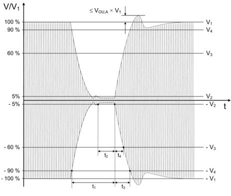
Figure 5. Parameter definition of EMV 3.0 for type A PCD-to-PICC interface waveform signal integrity tests.
The acceptable range of t3 is 0–1.18µs defined in EMV3.0. The value of 1.18µs corresponds to 16 carrier periods (fc). This means that the envelope needs to reach 90% of its full amplitude before 16 carriers.
The tuning of the overall Q is a trade-off between the RF power and the slew rate of its ASK modulation transitional edge. The higher Q boosts the current at the PCD antenna but increases t3. Figure 6 shows the simulation result of an example matching circuits with an ideal antenna model, with three different Q-tuning resistor values. This behavior is like a first-order LR circuit even though the PCD network is higher order and has much more complicated step response equation. Other than t3, t4 also has its specifications and is dependent on the overall Q. If t3 or t4 exceeds its upper limit, Q tuning resistor can be increased to lower t3 and t4 at the cost of RF power.

Figure 6. Impact of detuning resistor RQ on the rising time of type A 100% ASK signal. Red: RQ = 2Ω, Yellow: RQ = 5Ω, Blue: RQ = 10Ω.
Impact of the Loading Effect from PICC on Signal Waveform
The loading effect from PICC affects the RF power as well as the PCD-to-PICC signal waveform. In some cases, the loading effect can significantly break the inductive-capacitive balance of the matched circuit and introduce more undesired oscillatory behaviors.
Figure 7 shows the simulation result of an example matching circuit using an ideal antenna model, with three different levels of loading impacting the effective antenna inductance. Undesired overshooting is clearly seen when the matching condition is broken. Practically speaking, such severe loading effect does not happen until PICC is placed at a distance less than 1cm. Among the three PICCs and six different linear loads, PICC2 with high-linear load tends to have the strongest loading effect at 0cm and PICC3 has the least loading effect on the PCD. This is because PICC3 has smaller antenna and PICC2 is resonant at the carrier frequency of 13.56MHz. Therefore, it is recommended to check PICC2 high-linear load test cases at 0cm for overshoot/undershoot before other positions and PICCs. If it does not meet the specifications, there are multiple approaches to improve:
- Matching network redesign: Lowering the cutoff frequency of EMC filter helps reduce the loading effect. Also, the matching condition can be optimized for a certain loaded condition (for example, PICC2 high-linear load at 2cm) instead of being optimized for unloaded condition. In that case, the waveform at 3cm and 4cm is slightly mismatched, but at 0cm the deviation is less.
- Antenna redesign: Increasing the antenna size and/or decreasing the number of turns help reduce the loading effect however, there is a tradeoff considering the RF power.
- Product physical design adjustment: Moving the actual 0cm reference plane slightly away from the antenna coil plane is another helpful approach to solve this issue. This slightly reduces the power seen at longer distances.
- Firmware AFE tuning: The MAX32570 offers a firmware tuning of the four-step driver strength setting to reshape and smooth the waveform. More details of the four-step driver setting technique is described in the MAX32570 AFE Tuning Guide.
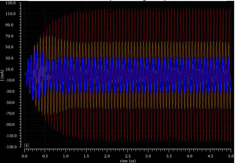
Figure 7. Impact of severe loading effect. Red: Matched condition with no loading effect, Yellow: Antenna-effective inductance changed by 200nH, Blue: Antenna-effective inductance changed by 400nH.
Type B PCD Signal Modulation Index Optimization
The details of Type B PCD signal modulation index tuning and dynamic AFE configuration are described in the AFE Tuning Guide. Also as already described in the Antenna Matching Design Guide, the dividing resistors before RXP and RXN can be optimized so that the FD level is maximized but still below its saturation point (255) at an unloaded condition. This way it helps increase the dynamic range of the FD level and makes it easier to separate the index steps. For EMV 3.0, it increases the complexity of planning and setting of the FD thresholds array and the AFE setting matrix as compared to EMV 2.6. It is recommended to prerecord the FD levels for the three PICCs with two different linear loads at five distances. Plot, as shown in Figure 8, helps visualize separation of the testing points into different step index groups. At each step index group, a Drive Low, or fd_dyn_sttm_bfv[31:24], value can be found that makes all the test points in this group pass the EMV modulation requirement. Since 10%–14% is the acceptable range (different distances have slight variation), tuning the modulation index to be around 11% or 12% is the best practice. Typically, the more sensitive a PCD is to the loading effect, the more variation of its modulation index is seen across different distances so that more separations are needed. Helpfully, stronger loading effect also increases the range of FD level, thus allowing more separations.
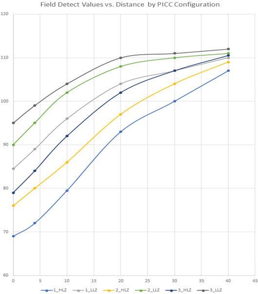
Figure 8. Example of a set of FD values for three PICCs with high-linear and low-linear loads at five different distances.
Type B Waveform Signal Integrity
It is important to note that other Type B waveform tests would be better to be performed after the modulation index test already passed. Because variation of the modulation index also impacts these test cases. The rising/falling edge timing and signal integrity of Type B signals follows the same rules as for Type A, therefore the procedure described earlier in this section also directly applies to Type B waveform. Normally, if a PCD hardware has already passed Type A signal integrity, it also passes for Type B. The MAX32570 offers firmware tuning of the four-step driver strength setting to reshape and smooth the Type B waveform separated from Type A tuning.
PICC-to-PCD Receiver Performance
The PICC-to-PCD signal interface test cases (TA131-TA138, TB131-TB138).x.1.zrf are the third group of test cases to execute after the RF power and PCD waveform signal integrity test cases have been passed. Even though this group of test cases take the most time to execute and debug, the tuning process is mainly related to firmware settings and less likely to be found necessary to change the hardware design of the PCD. Most of the AFE setting details for the receiver are already described in the AFE Tuning Guide, and in this document, some additional considerations are mentioned for EMV 3.0.
PCD Receiver Sensitivity
The receiver sensitivity of a PCD receiver is mainly determined by the phase noise of the 13.56MHz carrier delivered from the PCD. This is because other noise sources such as thermal noise are several orders of magnitude lower. A stable low jitter NFC clock source (crystal oscillator) at 27.12MHz is critical to ensure a good receiver sensitivity for the PCD. The phase noise of the carrier can be checked using a spectrum analyzer when tuning on the field without polling if the phase noise is below -124dBc/Hz at 848kHz offset from the carrier; it should be sufficient for MAX32570. The TA/TB135 at 2cm and TA/TB136 at 4cm are the best test case positions to check if the sensitivity is sufficient for EMV 3.0.
Hardware Considerations for Receiver Performance
The overall Q of the PCD determines its operating bandwidth. If the Q is too high the modulated PICC-to-PCD signal at 848kHz symbol rate may be degraded. However, since the PCD signal waveform integrity test already guaranteed the Q to be in a reasonable range, it is less likely at this point that PCD quality factor must be further reduced due to the receiver performance.
In addition, the dividing resistor at Rx chain should be set to a value that a reasonable large FD level can be observed at unloaded condition, and it is better not to be saturated at any loading condition of interest. This way it helps boost the signal strength feeding into the receiver. However, this step should have been done already during Tx Type B modulation index optimization.
Firmware Tuning of AFE Settings for the Receiver
The detailed procedure of Dynamic Firmware Receiver Setting tuning is described in the PCD AFE Tuning Guide. Similar FD level step index division planning can be done after collecting the FD level data at three PICCs with nonlinear load, a plot similar to Figure 8 helps visualize the overall FD level distribution of all test cases of interest in EMV 3.0. It is noted that for each position and PICC there are four different receiver test cases with different load modulation (minimum positive, maximum positive, minimum negative, and maximum negative) for both Type A and Type B protocols. It is crucial to optimize trigger level A and trigger level B and other dynamic AFE settings especially at the challenging positions.
Interoperability Test
Even though the interoperability test is separated from the EMV Analog test, technically it can be considered as an extension of the EMV Analog PICC-PCD receiver performance test. The difference is that the target PICCs are mobile card emulation devices in the market other than the EMVCo reference PICCs. The operating volume has slight differences in the covered positions. Typically, a PCD that passed EMVCo Analog test should almost automatically pass the interoperability test. It is because the upgrade of EMV3.0 tried to cover all the possible corner cases of different EMV-compliant PICC targets in the market. The interoperability tests include a collection of the mobile devices. These test devices are often swapped out per directions from EMVCo and are likely to be different in test labs in different regions. If there are challenging cases in the interop tests, it is recommended to be considered together with the analog receiver test cases when optimizing the dynamic receiver AFE settings.
Summary
Figure 9 shows a summary of the test cases related to EMV 3.0 Analog specifications. There are some other test cases such as Bit Level Coding Signal Interface tests that are self-guaranteed by the MAX32570 IC and its bundled firmware and do not require any additional design consideration. The recommended testing and debugging procedures are as follows:
- PCD-to-PICC RF power tests
- Type A Tx signal integrity tests
- Type B Tx modulation index and then other signal integrity tests
- PICC-to-PCD Rx tests, including Type A and Type B
To save time during the design and optimization iteration, corner cases such as those at 4cm and 0cm can be performed first before a reasonably good PCD hardware design and firmware setting are achieved.
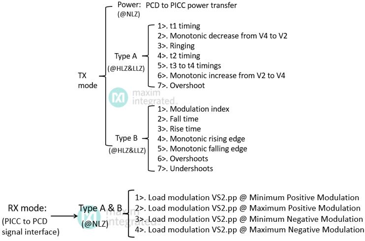
Figure 9. Summary of test cases in EMV 3.0 Analog.