AN-1518: 16-Bit, Fully Isolated, 4 mA to 20 mA, Output Module Using the AD5662 DAC, ADuM1401 Digital Isolator, and External Amplifiers
Circuit Function and Benefits
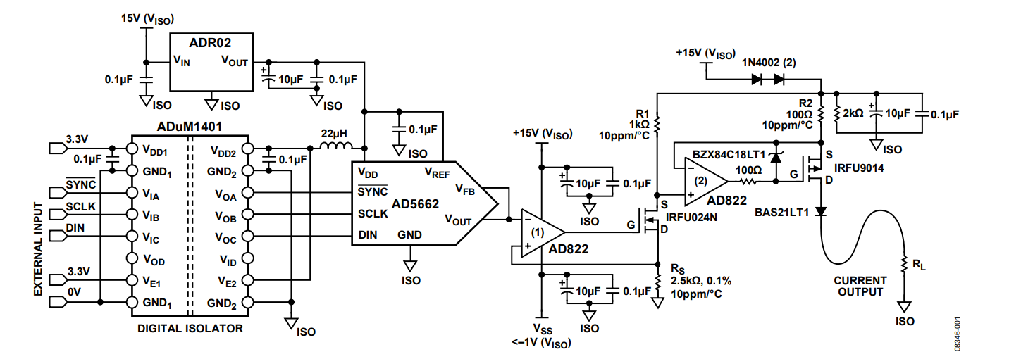
This circuit shown in Figure 1 provides a complete solution for an industrial control output module. This design is suitable for process control programmable logic controllers (PLCs) and distributed control system (DCS) modules and transmitters that require a 4 mA to 20 mA current output range. The AD5662 nanoDAC® is a 5 V, 16-bit, digital-to-analog converter (DAC) in a SOT-23 package. The ADuM1401 4-channel digital isolator provides signal isolation between the microcontroller and the DAC.

Circuit Description
For industrial control modules, analog output current ranges are typically 4 mA to 20 mA or 0 mA to 20 mA. The AD5662 provides a 0 V to 5 V output, which sets the current through the sense resistor, RS, and, therefore, the current through R1.This current is mirrored (10×) to R2, using the second half of the AD822 operational amplifier (op amp). The AD822 amplifier was chosen for its high performance and high voltage operation. The first stage of the current mirror must operate at 0 V input to prevent dead band when the DAC operates at zero-scale output. This 0 V input value requires that the negative supply to the AD822 be at least −1 V, guaranteeing sufficient headroom on the output of the first stage AD822. The two diodes in the second stage, which are in series with the positive power supply, ensure that the output voltage of the second stage does not go to the positive supply rail of the AD822, which can be as high as 35 V. The output of the field effect transistor (FET) is also protected by a series diode. This series diode increases the power dissipation of the circuit, which may be an issue in some applications.
The ADR02 has drift specifications of 9 ppm/°C maximum. It is also often used in industrial applications due to its high input voltage range of up to 36 V.
The ADuM1401 is a 4-channel digital isolator based on Analog Devices iCoupler® technology. The ADuM1401 provides isolation between the AD5662 and the system microcontroller, with an isolation rating of 2.5 kV rms. Three wires are used (SYNC, SCLK, and DIN), which connect the standard serial peripheral interface (SPI) connections to the AD5662.
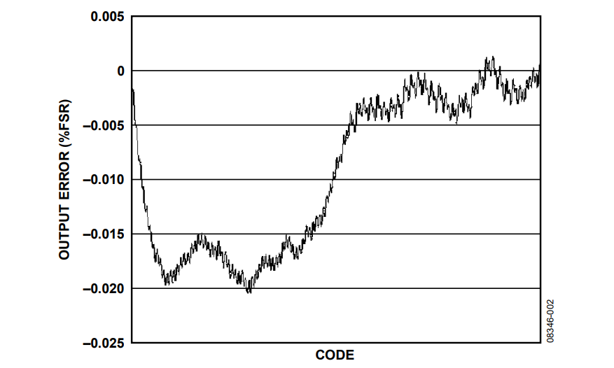
Figure 2 shows an integral nonlinearity (INL) accuracy plot of the current output of the circuit into RL when the AD5662 is used with the ADR02 external reference. Results are shown in percentage full-scale range (% FSR) as a function of input code. The ADR02 was chosen as the reference for this circuit.
See the Analog Dialogue article, “PLC Evaluation Board Simplifies Design of Industrial Process Control Systems,” for more discussion of external protection techniques.

References
MT-015 Tutorial, Basic DAC Architectures II: Binary DACs. Analog Devices.
MT-016 Tutorial, Basic DAC Architectures III: Segmented DACs. Analog Devices.