AN-006 N-MOS and P-MOS Power Stages
Understanding the Difference
Discrete Mosfet Power Bridges
Driving a two-phase bipolar stepper motor requires four half-bridges able to drive the motor current. The motor current is regulated using chopper operation at a frequency of several ten kHz. In order to drive a stepper motor at higher motor current, a driver chip using external MOSFETs is the most efficient solution. This is because discrete MOSFETs use a dedicated semiconductor technology different from the technology in integrated circuits. Furthermore, a discrete MOSFET is an extremely rugged and robust device. It is safe against overvoltage spikes up to a certain energy (due to zener effect), it is not easily destroyed by high temperatures (the devices will survive short term operation far in excess of 200°C) and provides an integrated reverse diode.
P Channel is the Natural Choice for High Side
Basically, there are two types of power MOSFETs: N channel and P channel devices. While an N channel device is the natural choice for a low-side switch, a P channel device is the natural choice for a high-side switch. In both configurations, the MOSFET's source terminal is connected to the supply voltage terminals (GND or VS) and the gate drive voltage is identical to this supply voltage for an off-state, or a gate control voltage in between of GND and VS for the on-state. This gate-to-source voltage typically lies in between 4.5V and 20V (N), respectively -4.5V to -20V (P). The TMC262, TMC389 and TMC239/249 family of stepper driver ICs use N&P channel power MOSFETs.
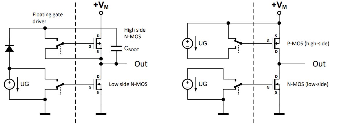
Many competitors’ products use N-channel MOSFETs also as high-side driver. In this configuration, Source and Drain are swapped when compared to the P channel MOSFET. The MOSFET then operates in a voltage follower circuit. Driving this MOSFET is more complex, because its gate now is related to the motor driver output, i.e., to a floating level rather than to a fixed level like a power supply rail. Additionally, its gate must be driven to a voltage higher than the positive supply voltage in order to switch on the MOSFET completely. Figure 1 shows both kinds of power stages for a half-bridge.

Figure 1. Comparing N&N-MOS Power Stage to N&P-MOS Power Stage
Difference in the Driver
A P channel MOSFET is the natural choice for a high-side driver. It is efficient, rugged and easy to control. Operation is possible up to the maximum supply voltage of the driver chip. A high-side NMOS gate driver is more complex and subject to issues at high dU/dt, because the driver itself is floating, i.e., its relative GND potential is identical to the driver output. Sometimes this is perceived when an unforeseen event (e.g., ESD event on the outer side of the motor) leads to an accelerated slope. As the slope is seen by the N channel high-side driver control chip directly, it might exceed the maximum allowable dU/dt. This can destroy the driver and lead to a sudden defect.
An N-channel high side driver also requires additional passive components to be supplied by the user: One bootstrap capacitor per high-side MOSFET is necessary in order to provide the high-side control voltage. A few devices use an additional common rail charge pump, which again requires two capacitors.
| Parameter | N&P power bridge | N&N power bridge |
| MOSFET Types | Many manufacturers offer half-bridge devices or single devices in the voltage range 30V to 60V. Examples are shown in the ADI TRINAMIC chip datasheets. | A single device type can be used for all MOSFETs. There are a huge number of single devices and a number of half bridge devices available. |
| Cooling via MOSFET drain terminal | The MOSFETs for each power half-bridge have a common drain terminal. Each half-bridge has a single electrical potential at the heat slug. An efficient single-heat slug package is possible for a half bridge device. | The low-side MOSFETs drain is tied to the half-bridge output, while the high-side MOSFET drain is at the positive motor supply voltage. There are five different electrical potentials for heat dissipation. When building a medium current driver with dual devices, a separated heat slug per MOSFET is still required. |
| On Resistance | P channel devices are less efficient than N channel devices. They have about 150% to 200% of the on-resistance RDSon at the same die size (i.e., same cost). This results from a P-channel device using minority carrier conduction. This fact has only minor influence on the half bridge power dissipation, due to much lower duty cycle on the high-side MOSFET. | On resistance is determined by the choice of MOSFET. Typically all MOSFETs, regardless of high-side or low-side, use are the same type and provide the same on resistance. |
| Gate Driver | Same principle as low-side driver, rugged device. | Floating driver is sensitive to damage by high dU/dt transients. |
| Additional parts for high-side control | No additional components required. | Floating driver requires bootstrap capacitors. This makes up for typically four additional passive components per stepper motor. |
| Voltage Range | The application benefits from the full voltage range covered by the gate driver technology. | The application voltage of the gate driver is reduced by the bootstrap voltage, typically 5 to 12V. |
Availibility
P channel MOSFETs have been rare on the market several years ago, but extended use in monitor backlighting inverters and switch regulators has led to an increasingly good availability within the last years. Many devices are available from large discrete component suppliers like Alpha and Omega, Fairchild, Infineon or Vishay. Increasingly a number of smaller and Asian suppliers offer a wide choice of devices with extremely competitive data, e.g., Diodes, Central semiconductor, APEC or UBIQ
Effective Resistance of the N&P Channel Half-Bridge
In order to understand the influence of the P channel MOSFET on the actual driver power dissipation, it is important to check the amount of time it conducts the motor current. The actual duty cycle depends on motor velocity, supply voltage and chopper settings. Typical duty cycles of a stepper motor coil in chopper operation within a microstep application range from 20% to 50% on-state duty cycle (for standby, low and medium velocity operation). The rest is slow decay duty cycle (i.e., 50% to 80%). The on-state duty cycle gives the conduction time for any high-side MOSFET. That means either one or the other high side MOSFET conducts. For the low side MOSFETs, at least one MOSFET is on all the time, i.e., 100% duty cycle for this MOSFET. The other MOSFET has a duty cycle of 100% (the high=side duty cycle), i.e., 50% to 80%.
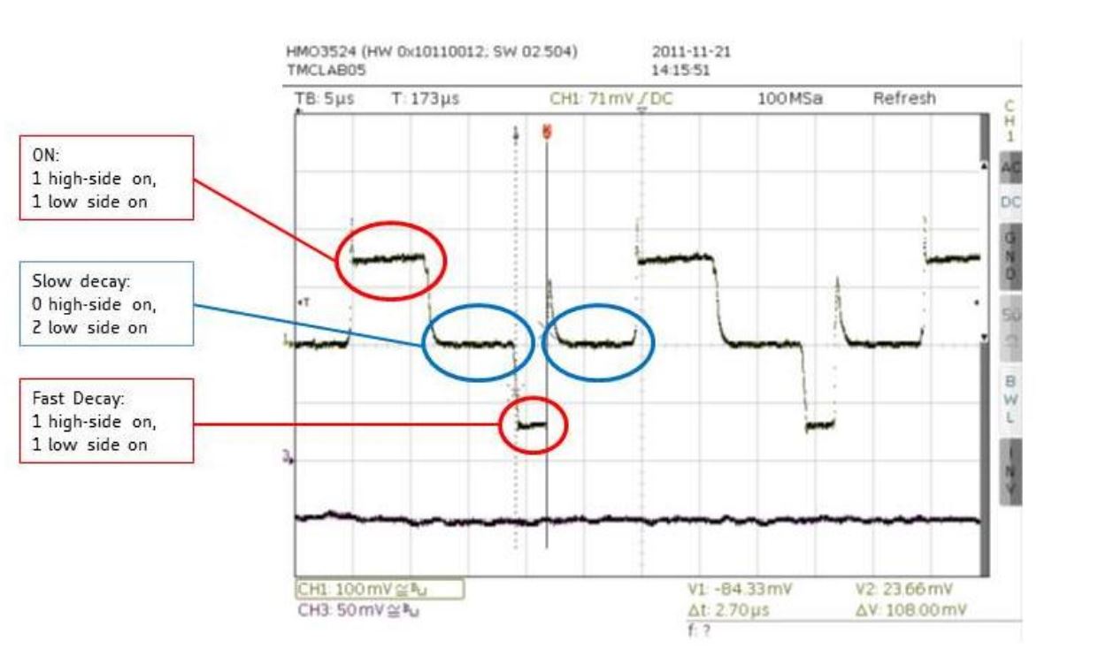
See Figure 2a for an example measured in an actual application (motor running) using a TMC262 and spreadCycle operation. The chopper cycle spans for 24µs, made up from roughly 7µs of on-time, 7µs slow decay time, 3µs negative on-state time (fast decay) and another 7µs slow decay time. The mean on-state duty cycle of a high-side MOSFET thus is (7+3)/24/2 = 20.8%. The mean on-state duty cycle for a low-side MOSFET is (24+14)/24/2 = 79.2%.

Figure 2a. On, Slow Decay and Fast Decay States as Seen on the Sense Resistor.
This means:
- A high-side MOSFET has a typical medium duty cycle of 10% to 25%.
- A low-side MOSFET has a typical medium duty cycle of 75% to 90%.
Thus the effective bridge resistance for an N and P channel bridge is mainly determined by the low-side, N channel MOSFET and has a lower dependence on the P channel MOSFET.
This is because the chopped operation of a motor uses the coil inductivity to store the energy. The voltage drop on the motor coil resistance therefore must be substantially less than the nominal supply voltage. Typically only a few volts of voltage drop in comparison to several 10 volts of supply voltage. This means that the medium duty cycle of the chopper (in operation at low velocities) is determined by the quotient of coil voltage drop and supply voltage. A slightly higher duty cycle results from mixed decay operation and from back-EMF at higher velocity motion. The ADI TRINAMIC ICs use the low side MOSFETs for re-circulation during slow decay phases. At high motor velocity, the chopper switches on for higher duty cycles up to about 90%, because the motor current cannot follow the desired target current anymore. On the other hand, the overall current drops in this mode and the number of chopper cycles reduces, thus reducing both static and dynamic power dissipation.
Example
A pure N channel MOSFET half-bridge based stepper driver is compared to an N&P channel half-bridge based stepper driver. Both designs shall show the same effective on-resistance. Assumption:
- Duty cycle high-side MOSFET = 20%
- Duty cycle low-side MOSFET = 80%
The P-channel MOSFET has a 1.75 times higher on-resistance than the N-channel MOSFET
| Parameter | N&P power bridge | N&N power bridge for comparison |
| Low-Side switch resistance | Rn | Rn1 |
| High-Side switch Resistance | Rp=1.75Rn (assumption) | Rn1 |
| Low-Side switch resistive power dissipation | I×Rn×80% | I×R1×80% |
| High-Side switch resistive power dissipation | I×Rp×20% | I×R1×20% |
| Resistive power dissipation for a half bridge | I×Rn×(0.8+1.75×0.2) = I×Rn×1.15 |
I×R1 |
| Required MOSFET resistance for same power dissipation | Rn=87%×R1 | R1 |
Result: In a mixed N&P bridge with the given assumptions, the actual on-resistance of the N-MOS must be 87% of the comparative pure N-channel bridge MOSFET, the actual on-resistance of the P-MOS can be 152% of the comparative pure N-channel bridge MOSFET in order to yield the same bridge power dissipation.
Calculation of Actual Power Dissipation
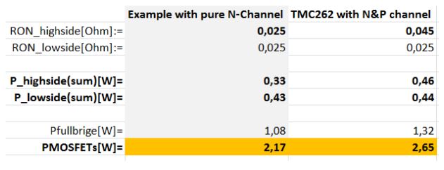
Please refer our product specific spread sheet to calculate the actual power dissipation of a bridge (e.g., TMC262_calculations.xls for the device TMC262). It also allows calculation of power dissipation using any MOSFET type described by its electrical data.

Figure 2b. Example Excerpt Showing N&N Bridge vs. N&P Bridge at 4A with identical NMOS
