Why Feedforward Capacitors Deserve a Spot in Designs: Tiny Component, Giant Leap

Why Feedforward Capacitors Deserve a Spot in Designs: Tiny Component, Giant Leap
2026-10-05
Key Takeaways
|
Abstract
Feedforward capacitors are a simple yet powerful enhancement in analog circuit design. By introducing a high-frequency path in the feedback network, they improve transient response and bandwidth. Commonly used in regulators, amplifiers, and precision analog systems, feedforward capacitors help circuits react faster and more smoothly to dynamic changes. Their implementation is straightforward, yet their influence on system behavior is profound. Engineers can leverage them to fine-tune loop dynamics and mitigate instability. This article explores their function, selection, design, best practices, and applications in Analog Devices’ controllers.
Introduction
Analog electronics demand precision, speed, and stability. Whether regulating voltage, amplifying signals, or conditioning sensor outputs, analog circuits must maintain consistent performance under varying conditions. Most analog systems rely on feedback loops to achieve this. These loops monitor the output and adjust the input to correct deviations, ensuring the system remains within its desired operating range.
However, feedback is inherently reactive—it only responds after a change has occurred. This delay can be problematic in systems with fast transient demands, such as those powering digital processors or sensitive analog front ends. The result can be overshooting, ringing, or even instability.
To mitigate these issues, designers often turn to feedforward capacitors. These capacitors are placed across the upper resistor in the feedback voltage divider and serve as a high-frequency bypass path. By allowing high-frequency components of the output to influence the control input directly, feedforward capacitors enable the system to respond more quickly and smoothly to changes. This proactive behavior also improves phase margin and noise suppression, making feedforward capacitors a powerful tool in modern analog design.
How Feedforward Capacitors Work
In analog circuits, feedback is used to regulate output by comparing it to a reference and adjusting it accordingly. While this mechanism is essential for maintaining accuracy, it has limitations particularly in how quickly it can respond to changes. The feedback loop’s speed is constrained by its bandwidth and phase margin, which are determined by the system’s compensation and component values.
A feedforward capacitor (CFF), typically placed across the upper resistor (R2) as illustrated in Figure 1 in a feedback voltage divider network, introduces a frequency-dependent behavior that enhances the loop’s responsiveness. Consider a typical feedback voltage divider with resistors R1 and R2 connected in series. The feedback voltage is taken from the junction of these resistors and fed into the control input of the regulator or error amplifier. When a capacitor (CFF) is placed across R2, it changes the impedance of the divider resistor at high frequencies, effectively allowing fast-changing signals to bypass the slower resistive path and reach the control input more directly.
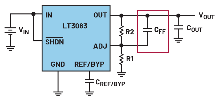
Technically, the feedforward capacitor introduces two key frequency elements into the loop gain.
• A zero at:

The zero frequency (fZ) increases the gain at frequencies above fZ, which helps the system respond more aggressively to rapid changes in output. It improves the phase margin and shifts the crossover frequency higher, resulting in faster correction of disturbances.
• A pole at:

The pole frequency (fP) counteracts the gain increase at even higher frequencies, ensuring that the system does not become unstable due to excessive amplification. It helps roll off the gain smoothly, maintaining control loop integrity.
The net effect is a bandwidth extension and phase margin improvement, which are crucial for systems that need to maintain stability while reacting quickly to load transients or input noise. Figure 2 shows the loop response with and without the feedforward capacitor. The feedforward capacitor essentially acts as a high-pass filter within the feedback path, allowing high-frequency components of the output to influence the control input without waiting for the slower feedback loop to catch up.
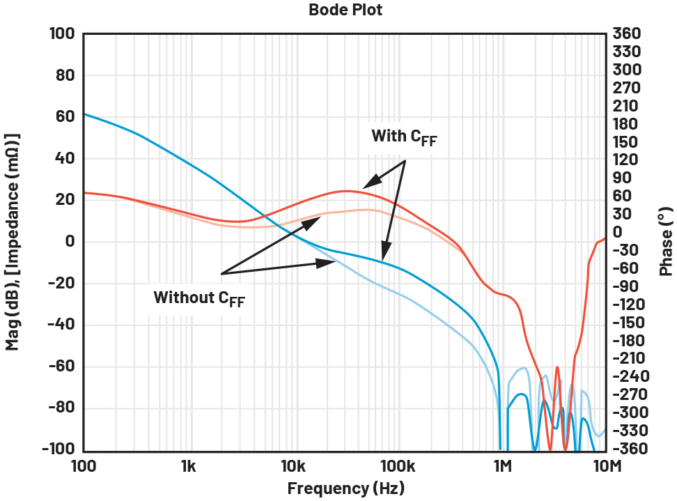
This behavior is particularly beneficial in systems with high-speed digital loads, where sudden changes in current demand can cause voltage dips or spikes. Without a feedforward capacitor, the feedback loop may react too slowly, resulting in poor transient performance. With the capacitor in place, the system can preemptively adjust, reducing overshoot and settling time.
Moreover, feedforward capacitors help suppress high-frequency noise that might otherwise be amplified by the feedback network. By shaping the loop’s frequency response, they reduce susceptibility to switching noise, electromagnetic interference (EMI), and other disturbances common in mixed-signal environments.
Selecting the Right Feedforward Capacitor
Selecting the appropriate feedforward capacitor is a critical step in optimizing analog circuit performance. The value of the capacitor directly influences the location of the zero and pole introduced into the feedback loop, which in turn affects the system’s bandwidth, phase margin, and transient response. A well-chosen capacitor can significantly improve stability and responsiveness, while a poorly selected one may lead to sluggish behavior or even instability.
The starting point for selection is understanding the values of the feedback resistors typically labeled R1 and R2 in a voltage divider configuration. These resistors set the gain and feedback ratio, and their interaction with the capacitor determines the frequency at which the zero and pole occur. The zero, created by the capacitor across R2, boosts gain at higher frequencies, while the pole, formed by the parallel combination of R1 and R2 with the capacitor, rolls off gain to prevent excessive amplification.
A practical formula to estimate the feedforward capacitor is:

where fCO is the desired crossover frequency, the point at which the loop gain crosses unity. For example, with R2 = 100kΩ and a target crossover frequency of 10kHz, the estimated capacitor value would be approximately 159pF. This value serves as a baseline, but real-world conditions such as parasitic capacitance, PCB layout, and component tolerances must be considered.
Simulation tools like LTspice® and LTpowerCAD® are invaluable for refining this estimate. It’s often beneficial to simulate a range of values from the calculated one, such as 10pF and 10nF, to observe how each affects overshoot, settling time, and stability. In general, smaller capacitors (10pF to 100pF) are suitable for fast systems where speed is critical, while larger capacitors (up to 1nF) are better for noise-sensitive applications that require smoother output and higher power-supply rejection ratio (PSRR). However, caution is needed: a capacitor that’s too large can slow down the system’s response and reduce its ability to track rapid changes, while too small a capacitor may not provide sufficient phase margin improvement.
Ultimately, selecting the right feedforward capacitor is a balance between speed, stability, and noise performance. It requires a combination of theoretical calculation, simulation, and empirical testing to ensure optimal results in the final design.
Transient Response Analysis
To illustrate the impact of feedforward capacitor values, Figure 3 shows the waveform comparing the transient response using the LT3063 low-dropout (LDO) regulator.
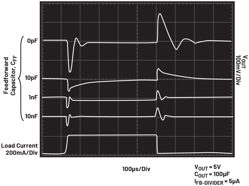
When using different capacitor values, the system’s response characteristics vary notably. In the absence of the capacitor, a sluggish response and huge overshoot is observed with some ringing. A 10pF capacitor results in a smooth response with noticeable reduction in overshoot, but the reaction is relatively slow. In contrast, a 1nF capacitor delivers a fast response with significantly reduced overshoot, making it more responsive. Meanwhile, a 10nF capacitor also provides a smooth response, though with only slight overshoot improvement from 1nF, balancing between speed and stability.
The overshoot and longer settling time are very evident when the feedforward capacitor is not fitted. Upon adding a capacitor, different values provide a glimpse of how it affects the response and overshoot levels. The added zero also keeps the phase from dropping too far, effectively preventing ringing in the output voltage. Evidently showing that the feedforward capacitor is essential during such scenarios. Designers must choose based on application priorities: speed, stability, or noise suppression.
Design Best Practices
Implementing feedforward capacitors effectively requires more than just choosing a value and placing it on the board. To truly benefit from their performance-enhancing capabilities, engineers should follow a set of best practices that address simulation, layout, component selection, and validation.
First, simulation is essential. Before committing to a design, use Analog Devices tools like LTspice or LTpowerCAD to model the control loop with a feedforward capacitor in place. These simulations allow designers to visualize the impact on gain and phase margins, observe transient behavior, and identify potential stability issues. Conducting simulations with various capacitor values enables a thorough analysis of their impact on system dynamics and assists in identifying the most suitable option.
PCB layout also plays a critical role in feedforward capacitor effectiveness. The capacitor should be placed as close as possible to the feedback resistors to minimize parasitic inductance and stray capacitance. Long traces or poor grounding can introduce unwanted delays or distortions in the feedback signal, undermining the benefits of the capacitor. Use short, direct routing and ensure a solid ground return path to maintain signal integrity.
In low-noise applications, such as RF systems or precision instrumentation, feedforward capacitors can help suppress high-frequency ripple and improve PSRR. In these cases, consider using capacitors with tight tolerance and low dielectric absorption to maintain consistent performance across temperature and voltage variations. Ceramic capacitors with negative-positive zero (NP0) dielectric are often preferred for their stability and low loss characteristics.
Finally, avoid overcompensation. While it may be tempting to use a large capacitor to eliminate all overshoots or ripple, doing so can lead to sluggish response or even instability. The goal is not to eliminate all dynamic behavior but to control it within acceptable limits. A well-compensated loop should respond quickly to changes without excessive ringing or delay.
By following these best practices: simulating early, selecting wisely, laying out carefully, and validating thoroughly engineers can unlock the full potential of feedforward capacitors and design analog systems that are both robust and responsive.
Integrating Feedforward Capacitors in ADI Products
ADI offers a wide range of high-performance components where feedforward capacitors are either recommended or supported to enhance system behavior.
One notable example is the LT3063, a micropower LDO regulator designed for noise-sensitive applications. The data sheet recommends a 10nF feedforward capacitor across the upper feedback resistor to improve load transient response and reduce output voltage noise. This is especially beneficial when operating at higher output voltages, where noise performance becomes more critical, transient overshoot/undershoot matters most, and system stability margins are tighter. The regulator is commonly used in battery-powered systems, automotive, and industrial where clean power delivery is essential.
The LTC3622 is a dual-channel, high-efficiency monolithic step-down regulator capable of operating from input supplies up to 17V. It features ultra-low quiescent current and supports fixed switching frequencies of 1MHz or 2.25MHz. In typical applications, such as dual-output converters delivering 3.3V and 5V, ADI recommends using 22pF feedforward capacitors across the feedback resistors to improve transient response and reduce ripple in the output. This recommendation is evident in ADI’s reference designs and application notes, where the capacitor helps stabilize the loop and enhance performance under dynamic load conditions.
Beyond these specific parts, ADI’s broader portfolio, including precision op amps and power management ICs, often supports feedforward capacitor integration as part of loop compensation strategies. In many cases, application notes and evaluation board schematics provide guidance on selecting and placing feedforward capacitors to optimize performance. ADI products demonstrate the practical value of feedforward capacitors across a variety of analog domains. Whether explicitly recommended in data sheets or supported through simulation and design tools, these capacitors offer a simple yet effective way to enhance circuit performance in real-world applications.
Conclusion
Feedforward capacitors might be small components, but their impact on analog system performance is profound. By introducing a high-frequency path in the feedback loop, they enable faster response to dynamic changes, reduce output noise, and improve overall stability. Their ability to shape the frequency response of a control loop makes them indispensable in precision analog design.
Whether applied in LDOs, switching regulators, or op amps, understanding and applying a feedforward capacitor can elevate a design from functional to exceptional. With careful selection, simulation, and layout consideration, these capacitors can be tailored to meet the specific requirements of a system.
In a world where analog performance is often judged by microvolts and microseconds, feedforward capacitors offer a simple yet elegant way to gain an edge. They are not just passive components, they are active contributors to smarter, faster, and more reliable analog systems.
关于作者
Hermogenes Escala是ADI公司欧洲、中东及非洲地区(EMEA)中央应用中心(CAC)的应用工程师。他深耕开关模式电源(SMPS)与电源管理领域,具有丰富的实操经验和深厚的技术见解。他拥有菲律宾东米沙鄢州立大学(EVSU)电子与通信工程学士学位和菲律宾马普阿大学电力电子研究生文凭。
加入ADI前,Hermo曾在多个行业担任设计与技术支持职务,涉足汽车仪表盘、音响系统、多领域电源设计及医疗设备等领域