
Good on Paper, Drifting in Flight: Vibration Effects in Drone IMUs
Key Takeaways
|
Abstract
Nominal inertial measurement unit (IMU) specifications are measured under quiet conditions and may not predict in-flight performance, where propulsion-induced vibration increases noise and can cause bias to drift. When external references are limited, these errors directly degrade navigation accuracy; in the evaluated first-responder scenario, they produced more than a 50× difference in position-tracking performance. For next-generation drones, vibration robustness must therefore be a primary IMU selection criterion.
IMU-Based Position Tracking in Drone Missions
Modern drone controllers do not rely on a single sensor. They combine global navigation satellite system (GNSS), vision, light detection and ranging (LIDAR), magnetometers, and microelectromechanical systems (MEMS) inertial measurement units (IMUs) to estimate motion and close the flight-control loop. Among these sources, the IMU has a specific job: it provides acceleration and angular-rate data at high speed and low latency, so the controller can stabilize the platform and follow the planned route between slower external updates.
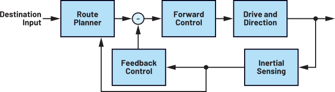
In practice, the IMU is the part of the sensing stack that the controller listens to most often, especially when responding to unexpected conditions. A typical navigation control loop is shown in Figure 1: the route planner requests a motion, the controller compares that request with IMU-derived attitude and motion estimates, and the resulting error signals drive thrust to perform orientation corrections.
The IMU bandwidth and dead reckoning performance become especially important in indoor first-responder missions, where the availability of external positioning references is inherently limited. The drone may have only a few minutes to enter a structure, locate a first responder, and report the position back to the rescue team outside, enabling them to quickly plan a safe entry route. As soon as it enters the building, GNSS reception becomes unreliable, while dust, smoke, darkness, and rapidly changing illumination can degrade vision-based positioning. Prior maps can also lose value when the environment has been altered by fire, collapse, or debris.
As external references disappear, inertial sensing becomes the primary source of position information, which means that even a small sensor bias can accumulate quickly. A simplified strapdown analysis shows why this accumulation becomes severe: an accelerometer bias, ba, is integrated into velocity and then position, so in a simplified one-dimensional case the position error grows quadratically as δx(t) = 1/2 ba t2 . Moreover, a gyroscope bias, bg, first appears as an attitude error, growing linearly as δθ(t) = bg t, but gravity and accelerations are projected onto the wrong navigation axes as a result, adding another position-error term that scales cubically with time.
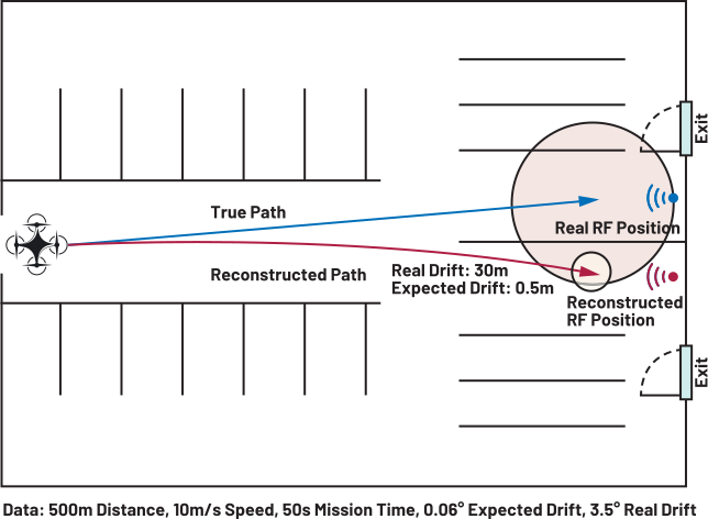
Figure 2 illustrates a firefighter rescue mission profile. The drone follows the responder’s RF signal toward the estimated location, covering a simplified 500m straight-line path in 50s (blue line). Compared with a rescue crew using handheld RF trackers, the drone can locate the responder faster while reducing the crew’s exposure to the hazardous environment.
To quantify the effect of inertial errors on trajectory reconstruction in this scenario, a drone test bench with spinning propellers was developed to reproduce the same conditions in a controlled but realistic way. On the platform, two IMUs were mounted side by side: a commercial IMU platform widely used in the drone market, and the ADIS16607, which is specifically designed with vibration rejection as a core requirement.
On paper, the two devices appear close enough: based on static data sheet metrics, each would be expected to accumulate only about 0.06° of yaw drift over the 50s mission window. Once the propellers are running, however, the commercial IMU drifts by 3.5°. In this simplified reconstruction, heading error maps directly into lateral displacement over the traveled distance, rotating the reconstructed trajectory (red line) away from the true path, and produces roughly 30m of lateral error after 500m (red area), compared with the 0.5m expected from the predicted value (yellow area), based on static noise metrics from the data sheet. In a rescue scenario, where both the person trapped inside the building and the outside team depend on that position estimate, this kind of error can send the rescue crew in through the wrong emergency door.
From Static Metrics to In-Flight Behavior
Data sheet metrics are still an appropriate starting point when comparing IMUs. Angular random walk, rate noise density, and in-run bias stability describe the nominal noise and bias floor of a device, and they are essential contributors to position, velocity, and angular error growth. The issue is not that these numbers are wrong; the issue is that they do not capture how the sensor behaves under dynamic motion, including vibration. Bias instability is typically characterized in controlled, mechanically stable conditions, while a drone places the IMU on a structure whose vibration changes with thrust, payload, propeller geometry, frame dynamics, and mounting conditions. Once the motors spin, the IMU is exposed to a mechanical environment that the laboratory setup was never meant to represent.
Vibration does more than increase the noise floor. In accelerometers, strong oscillatory motion can excite the spring-mass-damper structure nonlinearities, causing a bias shift, which appears as a nonzero average output even when the physical vibration is centered around zero. In gyroscopes, high-frequency vibration can couple into the sensing structure and be converted into low-frequency or quasi-DC rate error, a mechanism known as vibration rectification error (VRE). These effects explain why two IMUs with similar static specifications can behave very differently once mounted on a drone. While both accelerometer and gyroscope bias and noise floor are affected by vibration, accelerometer errors are mainly driven by vibration amplitude, while gyroscope errors depend strongly on the interaction between the drone vibration spectrum and the sensor’s mechanical design.
To see whether a real drone contains the ingredients for both effects, the vibration spectrum of our drone platform was measured, a 5-inch FPV GEPRC Mark 5 quadrotor equipped with Gemfan Hurricane 51366 propellers, using a laboratory-calibrated wideband accelerometer.
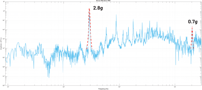
As shown in Figure 3, even at 50% thrust, the platform exhibits a 2.8g peak around 300Hz, large enough to challenge accelerometer linearity. The same spectrum also reaches into the kHz range, with 0.7g peaks at 20kHz, 23kHz, and 31kHz, where high-frequency content can couple into gyroscope resonant structures and greatly increase VRE.
The output transient in the two IMUs when motors are turned on is shown in Figure 4, confirming that vibration is a first-order effect in the tested environment.
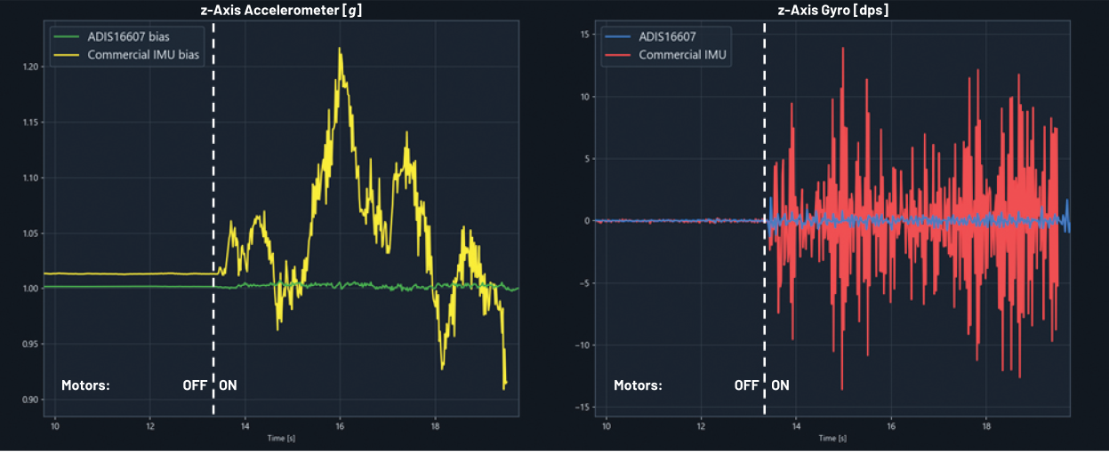
After turn-on, the commercial IMU exhibits peaks of 0.2g accelerometer bias shift and 13dps spurious gyroscope output, while the ADIS16607 remains comparatively stable under the same excitation.
The yaw estimate in Figure 5 makes the gyroscope error more explicit: integrating the commercial IMU z-axis gyro reveals both a quasi-DC drift component and a low-frequency oscillatory component, matching the expected VRE signature introduced by high-frequency vibration coupling into the sensor.
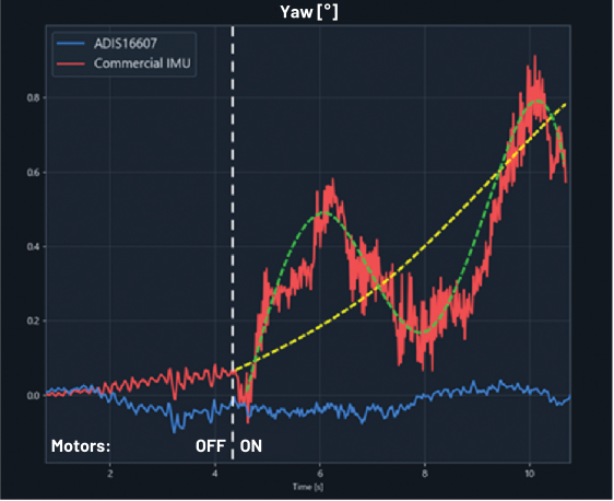
Within 6s after the motors are turned on, the commercial IMU already accumulates about 0.8° of yaw error. This confirms that the vibration-induced disturbances observed in the raw sensor data propagate into the attitude estimate used by the navigation stack.
Mitigation Layers and Their Limits
Mechanical Mitigation
After seeing an error at this scale, the first instinct is usually to attack the vibration mechanically. That can mean reducing the excitation at the source, limiting how it travels through the airframe, or isolating the IMU with a damping fixture. Propeller and frame design can help, but they quickly run into system-level trade-offs. Lower-vibration propellers may sacrifice thrust efficiency, and thus flight time, or responsiveness, while frame changes can shift resonances rather than remove them.
The IMU mount looks like the most direct place to intervene, because it targets the sensor before vibration reaches the measurements. In practice, however, damping is not a simple add-on, and it usually requires iterative mechanical design, finite element analysis (FEA), prototype testing, and validation on the final airframe.
Even after this effort, passive damping remains frequency-dependent and platform-specific, and its nonlinear response to large motions can introduce roll and pitch sway during aggressive maneuvers. More importantly, damping cannot selectively remove the quasi-DC or low-frequency components that appear after vibration has already been rectified by the sensor. Mechanical mitigation is useful, but it’s time-consuming to tune and hard to rely on as the only protection layer.
Digital Mitigation
After mechanics, the next instinct is to clean the signal in software. Low-pass filters can reduce broadband noise, and notch filters can suppress narrow vibration bands such as motor harmonics or frame resonances. These methods are useful when the disturbing frequencies are known or can be tracked. The challenge is that vibration-induced errors do not always remain at the original vibration frequencies. Once they enter the sensor, some of that energy can be converted into low-frequency or quasi-DC error, where it overlaps with the motion information the controller needs. This makes filtering much less reliable, because removing the disturbance may also remove part of the useful signal.
State estimation strategies can push mitigation further, but they also introduce new challenges. Model-based approaches such as Kalman filters can account for sensor noise and uncertainty, but only when vibration-induced disturbances are understood well enough to be represented in the model. This is rarely straightforward for VRE, whose temporal behavior depends on the vibration spectrum and sensor dynamics. Data-driven methods may capture more complex patterns, but they require extensive representative datasets and must still operate within embedded compute, memory, and latency constraints.
Digital mitigation is therefore a valuable cleanup layer, not a complete cure. It can suppress in-band vibration artifacts and improve robustness in known operating conditions, but it cannot reliably reconstruct information after vibration-induced error has already entered the useful signal band.
Sensor-Level Design
At this point, the message becomes clear: mechanical damping and digital filtering are valuable, but both intervene after the IMU has already produced its measurements. Once vibration is rectified into quasi-DC or low-frequency error, the application layer can only manage the disturbance, not fully remove it. Therefore, a more robust strategy is to also keep as much of that error as possible out of the signal path in the first place, which brings the problem back to the IMU architecture itself.
For accelerometers, the goal is to preserve linear response even under large vibration-induced displacements. Many sensors rely on static polynomial compensation to correct displacement-related nonlinearities. However, these nonlinearities can change with frequency, so a static correction cannot fully describe sensor behavior across the vibration spectrum. A more effective compensation scheme uses dynamic, frequency-dependent coefficients.
For gyroscopes, multimass architectures provide one path toward vibration rejection. By arranging proof masses to reject common-mode motion, they reduce the impact of translational vibration before it reaches the output. This helps, but it is not a complete shield. Rejection still depends on mass matching and drive symmetry; moreover, real drone vibration is not purely translational. Rotational components can excite the structures differentially, allowing part of the disturbance to bypass the common-mode rejection scheme.
This is where resonant-frequency placement becomes critical. Significant vibration spectral components have been measured up to the 30kHz range, so if the gyroscope resonance lies near the platform vibration spectrum, the sensor remains exposed to the mechanisms that generate VRE. This is the case with many gyroscopes in drone-class systems, with resonant frequencies in the 20kHz to 30kHz range. By pushing the resonance well above the dominant vibration content, the structure becomes harder to excite and less likely to demodulate the disturbance into the measurement band. A higher resonance frequency also reduces residual common-mode vibration sensitivity, because the common-mode response follows the sense-mode transfer function.
In the benchmark ADIS16607 device, these architectural choices help preserve the rated noise and bias behavior even with the motors running.
Vibration Robustness as a Next-Generation IMU Requirement
Next-generation drone platforms will place greater mechanical stress on inertial sensors as missions move toward GNSS-denied navigation, higher payloads, tighter control loops, and more aggressive flight profiles. In these conditions, vibration robustness cannot remain an accessory specification, and it cannot be delegated entirely to mounting hardware or software filtering. Once vibration has been converted into bias shift or VRE inside the sensor, the rest of the system can only manage the error, not fully recover the lost information.
The practical implication is clear: static data sheet metrics are necessary, but not sufficient to predict the IMU response to dynamic maneuvers and vibration. Bias stability, noise density, bandwidth, and power still matter, but they must be considered together with how the IMU behaves under the mechanical spectrum of the actual platform. The experimental results presented here show why this distinction matters. Two IMUs that look comparable on paper can produce radically different navigation outcomes once the motors are running, turning a nominally small error into meters of position uncertainty.
Drone developers are increasingly looking beyond quiet-bench specifications and asking whether an IMU can preserve its rated performance under real propulsion-induced vibration. The selection question therefore changes from “Which IMU has the best specifications?” to “Which IMU can preserve those specifications in the vibration environment of my aircraft?”
Devices that combine dynamic accelerometer compensation and high-frequency gyroscope design within a vibration-aware architecture offer a more reliable path to maintaining inertial performance in flight. As drones take on missions where external references are limited and position error directly affects mission success, vibration robustness becomes not a secondary feature, but a core requirement for the next generation of IMU-enabled platforms.