Sub-µA RMS Current Measurement for Quartz Crystals
Quartz crystal RMS operating current is critical to long-term stability, temperature coefficient and reliability. Accurate determination of RMS crystal current, especially in micropower types, is complicated by the necessity to minimize introduced parasitics, particulary capacitance, which corrupt crystal operation.
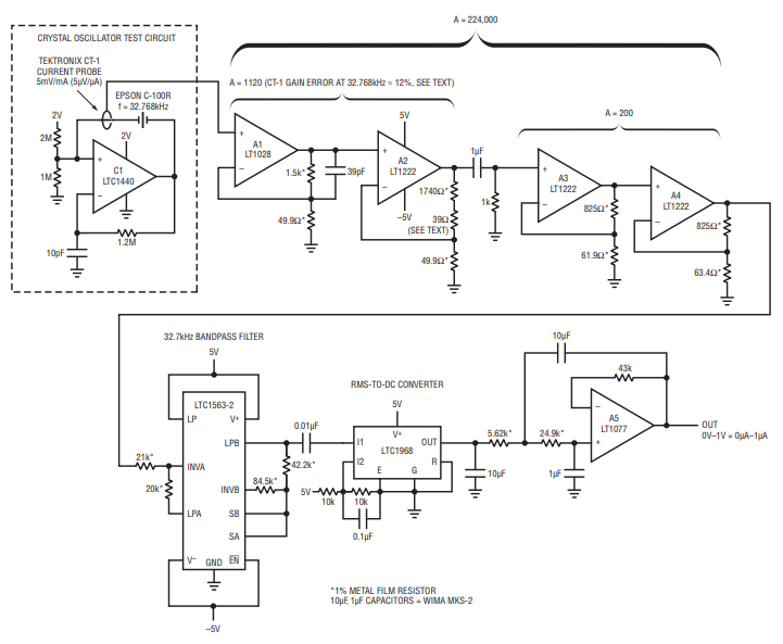
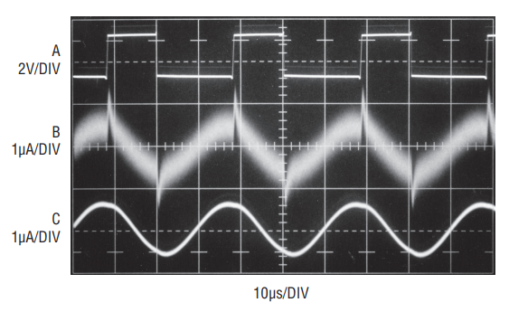
Figure 1’s high gain, low noise amplifier combines with a commercially available closed core current probe to permit the measurement. An RMS-to-DC converter supplies the RMS value. The quartz crystal test circuit shown in dashed lines exemplifies a typical measurement situation. The Tektronix CT-1 current probe monitors crystal current while introducing minimal parasitic loading. The probe’s 50Ω terminated output is fed to A1. A1 and A2 take a closed loop gain of 1120; excess gain over a nominal gain of 1000 corrects for the CT-1’s 12% low frequency gain error at 32.768kHz.1 A3 and A4 contribute a gain of 200, resulting in total amplifier gain of 224,000. This figure results in a 1V/µA scale factor at A4 referred to the gain corrected CT-1’s output. A4’s LTC1563-2 bandpass filtered output feeds an LTC1968-based RMS-to-DC converter (A5), which provides the circuit’s output. The signal processing path constitutes an extremely narrow band amplifier tuned to the crystal’s frequency. Figure 2 shows typical circuit waveforms. Crystal drive, taken at C1’s output (trace A), causes a 530nA RMS crystal current, which is represented at A4’s output (Trace B) and the RMS-to-DC converter input (Trace C). Peaking visible in Trace B’s unfiltered presentation derive from inherent and parasitic paths shunting crystal.

Figure 1. Op amps A1–A4 furnish gain of > 200,000, permitting sub-µA crystal current measurement. The LTC1563-2 bandpass filter smooths residual noise while providing unity gain at 32.768kHz. The LTC1968 RMS-to-DC converter supplies RMS calibrated output.

Figure 2. The 32.768kHz output of the crystal oscillator (Trace A) and crystal current monitored at A4 output (Trace B) and the RMS-to-DC converter input (Trace C). Peaks in Trace B’s unfiltered waveform derive from inherent and parasitic paths shunting the crystal.
Typical circuit accuracy is 5%. Uncertainty terms include the transformer’s tolerances, its approximately 1.5pF loading and resistor/RMS-to-DC converter error. Calibrating the circuit reduces error to less than 1%. Calibration involves driving the transformer with 1µA at 32.7kHz. This is facilitated by biasing a 100k, 0.1% resistor with an oscillator set at 0.1V output. The output voltage should be verified with an RMS voltmeter having appropriate accuracy. Figure 1 is calibrated by padding A2’s gain with a small resistive correction, typically 39Ω.
Notes
1 The validity of this gain error correction at one sinusoidal frequency—32.768kHz—was investigated with a 7-sample group of Tektronix CT-1s. Device outputs were collectively within 0.5% of 12% down for a 1.00µA, 32.768kHz sinusoidal input current. Although this tends to support the measurement scheme, it is worth noting that these results are as measured. Tektronix does not guarantee performance below the specified –3dB, 25kHz low frequency roll-off.


