摘要
Li-ion batteries pack the most power per unit volume, but excessive charging or discharging can damage or destroy the battery and its surroundings. Carefully designed circuits can help you avoid such dire consequences.
Lithium-ion (Li-ion) batteries are now the popular choice for applications that require the highest concentrations of available power, both per unit volume and per unit weight. These batteries can store more energy than NiCd, nickel-metal hydride (NiMH), and other rechargeable types. Battery manufacturers developed Li-ion technology to avoid the problem of the volatility of metal lithium (see the appendix, "Why Lithium?"). The absence of lithium metal exempts Li-ion batteries from the shipping regulations that apply to primary cells, so they can be larger and have greater capacities.
However, Li-ion batteries are not indestructible. They require strict adherence to the rules for charging and discharging. Ignore the rules, and you risk reducing battery life or destroying the battery and its surroundings. As a fail-safe measure, battery-pack manufacturers often include a protection switch that prevents excessive charging or discharging of the battery. Specialized charge and discharge circuits also prevent these conditions.
Consider Charge Circuits First
Unfortunately, there is no single set of rules for charging Li-ion batteries. Because Li-ion-battery technology is so new, the rules and requirements for battery charging tend to vary with the manufacturer. A typical charger must first provide a constant-current source and then a constant float voltage (the level considered nominal for a fully charged battery) as the charge terminates. The design of this combination current-and-voltage source is tricky, because the output impedance must be high for the current source and low for the voltage source.
Charging current depends on the battery's size and capacity, and the necessary current varies from a few hundred milliamps to about 2.5A. The exact Li-ion-battery chemistry varies with the manufacturer and is generally proprietary, but the resulting termination voltage typically varies from 4.2 to 4.3V per cell. Although accuracy for the charging current is around ±10%, the requirement on the termination voltage is typically ±1%.
Choose a Charger Topology
Battery chargers generally use a linear regulator to control the battery current or voltage. The input voltage to the charger is thus higher than the battery voltage, and a pass transistor drops the difference between the two voltages. Though simple and inexpensive, this approach can be inefficient.
Efficiency is not important for standalone units powered by the AC line or a car battery; however, because battery packs and systems have become more complex, the charger circuit often must reside in the portable equipment or in the battery pack itself. Such systems provide sufficient power to the charger by design, but inefficient circuitry can generate excess heat that causes problems in other parts of the system.
The following example illustrates how much heat a charger can generate. A charger powered by 8V±20% and charging one Li-ion cell at 1A produces a typical power dissipation of 1A(8V-3.8V) = 4.2W. The worst-case dissipation is 1A((1.238V)-2.5V) = 7.1W, which means that the charger is probably dissipating more power than the system. If the charger is built into the battery pack, much of the resulting heat goes into the battery, shortening the battery life and creating a potential safety hazard.
Linear-regulator chargers are often unacceptable because of their power dissipation, so designers usually opt for the cooler, more efficient switch-mode charger. A transistor in the switch-mode regulator turns on and off the way a power switch does, making abrupt transitions between the states of cutoff and saturation. This action creates a rectangular wave that passes through an inductor/capacitor filter to achieve the desired voltage or current.
Switch-Mode Chargers Run Cooler
Power dissipation in a switch-mode regulator is usually much less than that of a linear regulator; typical switchers are 80% to 90% efficient. For the example above, a typical switching regulator operating at 80% efficiency offers a considerable improvement over the linear regulator. The switcher dissipates 3.8V31A((1/0.80)-1) = 0.95W (typical) and 4.2V31A((1/0.80)-1) = 1.05W (maximum).
Switch-mode chargers have drawbacks, however. Their costly LC passive filters compare with the all-active components of linear chargers, which in IC form are relatively inexpensive. Also, the noise in a switch-mode charger is much greater than that of a linear type. For cell phones and other noise-sensitive applications, the presence of power switching can produce conducted or radiated interference in the system. You can prevent these problems by proper bypassing and shielding and by selecting a switching frequency that avoids the audio, RF, and IF bands.
The LC filter can represent a large part of the cost of a switch-mode charger, so it pays to reduce the size and the cost of this filter by increasing the switching frequency. On the other hand, too high a frequency lowers the charger's efficiency, which undermines the main benefit of using a switch-mode charger in the first place.
Switching losses occur mainly in the switching transistor. Current and voltage levels are relatively high during the brief transition intervals between the on and off states, and these levels cause power dissipation that is proportional to the switching frequency. Designers rarely use bipolar transistors in these applications, because these transistors cannot exit the saturation state fast enough for efficient operation at high frequency. MOSFETs, on the other hand, perform well if a sufficiently low impedance source drives their high-capacitance gate.
Switching Losses Degrade Performance
On-resistance is the other major source of loss in a switching transistor. A MOSFET in saturation, for example, appears as a resistance between the drain and the source. Higher on-resistance means higher power dissipation, but device technology has considerably lowered this resistance. However, lowering the on-resistance generally increases the gate capacitance, which in turn increases the switching losses. Thus, you have to choose the MOSFET carefully to lower the overall power dissipation.
Another drawback to high-frequency switching is the power lost in charging and discharging the switching MOSFET's gate capacitance. This loss is most conspicuous in its effect on light-load efficiency. You can minimize the loss by controlling the switching transistor using pulse-frequency modulation (PFM) rather than pulse-width modulation (PWM).
PWM circuits operate at a fixed frequency and regulate VOUT by adjusting the switching transistor's duty cycle. PFM circuits turn on the transistor for a fixed interval and regulate VOUT by adjusting the frequency of those intervals. For lightly loaded regulators, therefore, PFM control consumes less power, because the power transistor switches at rates as low as a few hertz. For heavier loads, the typical switching frequencies for PWM and PFM regulators are in the hundreds of kilohertz.
Deal with Stability
Stability is among the most difficult issues in designing a charger for Li-ion batteries. As mentioned earlier, the charger output must serve as both a voltage source and a current source. Unfortunately, it's difficult to make the circuit operate well in both modes because the requirements are contradictory; the current source should have high source impedance, and the voltage source should have low source impedance. The slow rate of change of battery voltage and current during charging somewhat mitigates the stability problem. However, input voltage from a poorly regulated AC adapter can include a substantial 60Hz or 120Hz ripple that can affect the charger's voltage and current regulation.
Analyze Some Real Circuits
The charger designs that follow all conform to the needs of Li-ion batteries, switching from current to voltage regulation. Each circuit shows you a different charger design, with various amounts of charging current, for example, to suit a variety of application requirements.
The step-down charger in Figure 1a regulates current into a discharged battery, while monitoring the battery's rising terminal voltage. When this voltage reaches the float voltage set by R1 and R2 (4.2V in this case), the circuit shifts from current to voltage regulation and maintains the float level as battery current tails off. The configuration in the figure charges one cell, but the circuit can handle as many as three Li-ion cells in series. The circuit also delivers load current while charging a battery.
The 0.1 resistor, R3, which drops 10mV at the maximum-allowed current of 100mA, senses the battery current. Op-amp IC2 amplifies this 10mV drop with a gain of 128 and presents a threshold voltage of 1.28V at IC1's feedback terminal. Thus, the circuit maintains a 100mA battery current until its terminal voltage reaches 4.2V, which causes the shunt regulator (IC3) to conduct current and bias Q1 into the active region. As Q1's collector sources current into R4 and R5, the op amp maintains equilibrium in the loop by lowering its output voltage. This action shifts the control from current regulation by the op amp to voltage regulation by the shunt regulator, which assumes full control as the op amp's output reaches 0V.
The shunt-regulator accuracy is 0.4%, so using 0.5% resistors ensures a 1% tolerance for the output voltage. You can calculate VOUT by noting that the regulator's feedback voltage is 2.5V: VOUT = 2.5((R1+R2)/R2). The regulated current is
IOUT = VREF3R6/(R33(R5+R6)), where VREF = 1.28V.
For light-load currents, the efficiency is low because of the fixed quiescent power dissipation (Figure 1b). This figure shows how efficiency and output power change from the beginning to the end of the charging cycle. The figure also shows the circuit's change from current to voltage regulation.
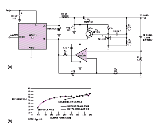
Figure 1. This step-down battery charger (a) delivers 100mA until the battery voltage rises to 4.2V and then regulates at that voltage until the charging is complete. Maximum efficiency occurs at high output power (b), and efficiency increases as VIN decreases.
Because the drop across D1 is more significant for low VOUT, the efficiency during current regulation is also proportional to low output voltage. Maximum power indicates the point at which the charger shifts from current- to voltage-regulation mode. Thus, the charger first delivers 250mW to a discharged battery, peaks at 420mW, and subsides to zero when the battery is fully charged.
Provide More Current
The greater current capability of an external switching MOSFET is useful in circuits that provide more than 200mA of charging current (Figure 2). This circuit regulates output current at 1A, but the MOSFET enables the charger to supply more than 2.5A of combined load and battery current. This circuit regulates the output voltage at 8.4V, but the voltage- and current-regulation circuitry is similar to that shown in Figure 1a. Also, like the circuit in Figure 1a, this circuit can charge as many as three Li-ion cells in series. You calculate VOUT and IOUT for Figure 2 as for Figure 1a, except the IC's reference voltage in Figure 2 is 1.5V instead of 1.28V.
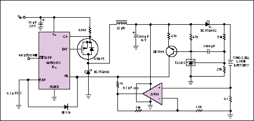
Figure 2. For applications that require more than 200mA of charging current, this circuit employs a switching MOSFET external to the controller IC.
Step-up Battery Charger
The charger in Figure 3 is similar to those in Figures 1 and 2, but it employs a step-up converter (IC1) that enables the circuit to operate from voltages lower than that of the battery. One problem with this circuit is the DC path from the input to the battery, which allows an uncontrolled current through the battery whenever VIN exceeds the battery's terminal voltage. Li-ion cell voltages should never fall below 2.5V, so VIN should never rise above 2.5V per cell.
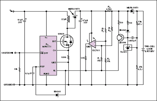
Figure 3. This step-up battery charger regulates at 0.4A in current mode and 8.4V in voltage mode. A DC path from input to output becomes a problem if VIN exceeds the battery voltage.
Current-sense resistor R1 and common-mode-amplifier resistors R2 to R5 determine the battery current. (R2 and R4 should have the same value, as should R3 and R5.) The regulated current, IOUT, equals VREF3R2/R33R1. In this case, VREF = 1.5V, which sets IOUT = 0.4A. When the voltage-regulator circuitry takes control, as in the chargers in Figures 1 and 2, the battery voltage regulates at 8.4V.
Operate at a Fixed Frequency
Many applications require that switching converters and chargers operate at a fixed frequency. Otherwise, the variable-frequency switching noise can interfere with sensitive circuitry, such as RF, IF, and audio amplifiers. In Figure 4a, for example, the step-down DC/DC converter (IC1) has an internal oscillator whose frequency can be user-selected at a fixed value of 150kHz or 300kHz, or synchronized with an external clock.
This charger also substitutes an external synchronous-rectifier MOSFET, Q2, for the Schottky catch diode in conventional step-down converters. (A Schottky diode, D1, remains in parallel with the MOSFET to prevent discontinuities in the current waveform.) The synchronous-rectifier MOSFET acts as a rectifier whose switching is synchronized with that of the converter. This arrangement improves efficiency, simply because the MOSFET's voltage drop is lower than that of a catch diode. This advantage is especially important in low-VOUT applications, in which the diode drop represents a substantial fraction of VOUT. A second Schottky diode (D2) prevents current flow from the battery in the event of a low VIN or input short circuit. The result is lower efficiency, but not as low as that of a conventionally rectified circuit.
During current-mode control, IC1 monitors the inductor current as a drop across R1, sensed by op-amp IC2 and resistors R2 to R5. The control circuitry is similar to that in Figure 3. This circuitry regulates the battery current to 2.5A±10% and then regulates the battery voltage to 4.2V±1%. A low-dropout, 5V regulator internal to IC1 produces a supply rail (the VL bus) that powers the internal control circuitry and MOSFET drivers. Thus, VIN can rise to 30V without driving the MOSFET gates beyond their absolute maximum ratings. To minimize power consumption, the VL bus's external-load capability (5mA at 5V) can power a low-voltage op amp for IC2.
Because Q1's transition losses increase with VIN, the measured efficiency for this circuit degrades slightly as VIN increases (Figure 4b). The drop across D2 is significant in comparison with low VOUT, so the efficiency during current regulation (as in Figure 1b) is noticeably proportional to VOUT. Under most conditions, this circuit provides efficiencies in the neighborhood of 85%.
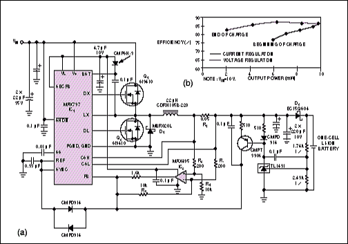
Figure 4. The controller IC in this battery charger (a) controls the switching-noise spectrum by operating at a fixed frequency. Efficiency curves (b) show that the charger delivers 6W at the beginning of a charge, peaks at 10W, and trails off to 2W as the charging terminates.
The charger in Figure 5a is similar to that in Figure 4a, except that this charger can handle batteries with more than one cell in series. This circuit charges two cells at 300mA. Voltage dividers R2/R3 and R4/R5 reduce the current-sense voltage across R1 to a level suitable for the controller. The internal current-sense amplifier has a common-mode range of 2V to 6V. To avoid introducing an offset, you should use 1% resistors in the voltage dividers.
Also, C1 and C2 counteract the pole formed by the divider resistors and the parasitic capacitance associated with the controller's CSH and CSL pins. This circuit regulates VOUT to 8.4V; otherwise, it is similar to the one-cell version in Figure 4a. Figure 5b shows this charger's VOUT/IOUT characteristics, and Figure 5c illustrates its efficiency versus output power for various values of VIN.
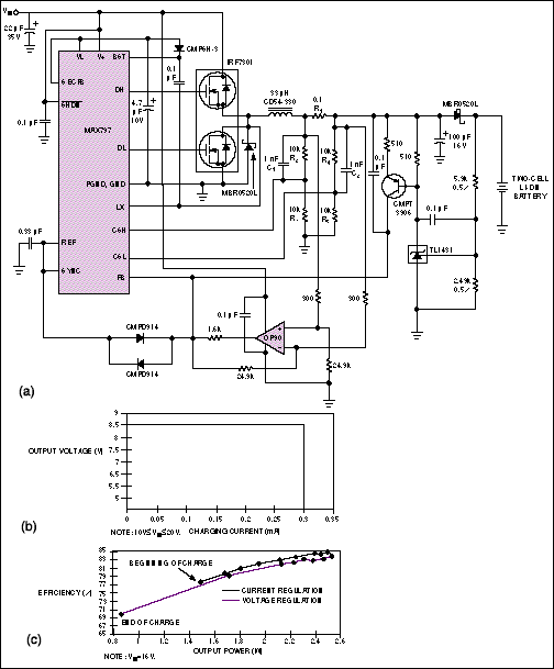
Figure 5. This Li-ion battery charger (a) delivers 300mA for charging two cells in series. Two graphs illustrate the circuit's performance: VOUT vs. IOUT (b) and efficiency vs. output power for input voltages of 10V to 20V (c).
Don't spend all your design effort on the charger alone; Li-ion batteries are sensitive to overdischarge as well as overcharging. For most of these batteries, discharge below 2.5V reduces the battery capacity. To prevent this problem, most Li-ion battery packs include a sensing circuit and MOSFET that disconnect the load if battery voltage drops too low (Figure 6).
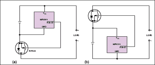
Figure 6. These circuits protect a Li-ion battery by preventing discharge below 2.5V. The mP-supervisor ICs block the battery current by driving the gate of an n-channel MOSFET low (a) or a p-channel MOSFET high (b)
Each of the circuits in Figure 6 includes a µP-supervisor IC designed to issue a reset to a µP when its supply voltage drops out of regulation. In this case, the supervisor controls a MOSFET that disconnects the battery from the load at the preset threshold of 2.63V, thereby preventing the battery voltage from dropping to 2.50V. The ICs come in tiny SOT-23 packages. When combined with a Micro-8-sized MOSFET (International Rectifier, El Segundo, CA), the result is a small circuit suitable for use inside a battery pack.
In Figure 6a's circuit, normal operation provides a positive voltage to the gate of an n-channel MOSFET, allowing battery current to flow to the load. When VCC drops below the reset threshold, gate voltage goes low and turns off the MOSFET. In contrast, Figure 6b's circuit supports normal operation with a low-level gate drive to a p-channel MOSFET and flags the low-VCC condition by driving the MOSFET gate high.
N-channel MOSFETs have lower on-resistance than do equivalent p-channel types, so the circuit in Figure 6a has less MOSFET loss than does the circuit in Figure 6b. However, some battery packs include fuel-gauging and voltage-sensing circuitry that is referenced to the battery ground. When the MOSFET in Figure 6a is off, the circuit grounds the battery's positive terminal through the load terminals, forcing the negative terminal and any associated signals to be negative with respect to the load. This condition can disrupt the system.
The simple circuits in Figure 6 have some drawbacks. Trip-level accuracy of the supervisory ICs is approximately ±5% over temperature, so you must set the nominal trip level at least 5% above the battery's minimum terminal voltage. Thus, in some cases, the battery and the load can disconnect before VCC reaches the desired threshold, leaving unused charge in the battery. Another drawback is the absence of hysteresis in the switching action. Battery voltage rises when its load is removed, thereby removing the drop across the battery's internal impedance. This rise can allow the load to reconnect, then disconnect, then reconnect, and so on. Cycling continues until the battery's open-circuit voltage falls below the reset threshold.
An alternative circuit structure resolves these problems using an additional comparator and voltage divider (Figure 7). You can program these circuits with enough hysteresis to prevent cycling, and the use of resistors with sufficient precision lets you set the threshold level to within ±2%. (The comparator's reference accuracy is ±1%, so 1% resistors yield an overall accuracy of about ±2%.) The circuit biases the voltage divider at 1 µA, which is low enough to minimize battery drain yet high enough to avoid a level shift due to the comparator's maximum input-bias current of ±5 nA.
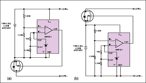
Figure 7. As improvements over their Figure 6 counterparts, these circuits have more accurate reset thresholds to save battery energy and hysteresis to prevent chatter as the battery disconnects.
Appendix
Why Lithium?
Lithium batteries have existed for years, mainly as primary (nonrechargeable) types in the form of small "coin" cells. Larger primary cells are considered hazardous materials and are not widely available in the United States. Lithium is a very reactive element; this is good for batteries but dangerous because its reactivity makes it potentially flammable.
For normal shipping, the U.S. Department of Transportation limits the amount of lithium in a single cell to 1g. Solid-electrolyte lithium cells (lithium-iodine and lithium-manganese-dioxide types, for example) have high internal impedance, which limits their use for pacemakers and other low-current long-life applications. You can discharge liquid-cathode lithium cells at a higher rate, but these types are generally limited to memory-retention and battery-backup applications.
Rechargeable (secondary) lithium batteries appeared in the 1980s. These batteries use lithium metal as the negative electrode (the anode) and an "intercalation" positive electrode (the cathode). Intercalation refers to an electrochemical reaction in which ions bond to the cathode material. Because this reaction is reversible (deintercalation), the battery can be made rechargeable.
When a rechargeable lithium battery discharges, the lithium metal gives off ions to the electrolyte, which is either a liquid or a solid polymer. These lithium ions migrate to the cathode and ionically bond with that material. The main problem with this battery type is dendrites: small fingers of lithium metal that form while the battery is charging. Dendrites increase the metal's surface area, producing a greater reactivity with the electrolyte. Thus, the battery becomes increasingly sensitive to abuse, because the number of dendrites increases with each charge-discharge cycle.
Remove the Metal
To overcome the problems associated with lithium metal in batteries, researchers experimented with the use of intercalation materials for both the anode and the cathode, producing a component known as the lithium-ion (Li-ion) battery. Lithium metal is not present; instead, positively charged lithium ions travel from the cathode to the anode during charge and from the anode back to the cathode during discharge. This back-and-forth ion flow during the charge and discharge cycles has led to the expressions "swing" and "rocking-chair" batteries.
The use of intercalation electrodes not only eliminates the need for lithium metal but also simplifies manufacturing, because manufacturers can construct the battery at zero potential. The manufacturer can then charge the battery after assembly, thereby reducing the possibility of damage due to short circuits.
The first Li-ion battery had a carbon anode and a LiCoO2 cathode and was manufactured by Sony Energytec. Other manufacturers since then have developed cathodes based on LiNiO2 and LiMn2O4, but all (so far) use carbon for the anode. This carbon anode stores the electrons and lithium ions during charge and releases them during discharge.
A similar version of this article appeared in the December 5, 1996 issue of EDN.


