
Mitigating Watchdog-Induced 100% PWM Fault States in HDD Cooling Systems
Key Takeaways
|
Abstract
This article addresses a critical failure mode in high-density hard disk drive (HDD) cooling systems: the default 100% PWM duty cycle triggered by fan controller watchdog timeouts. While 100% duty cycle protects silicon from overheating during a BMC hang, the resulting surge in mechanical vibration and acoustic pressure often leads to track misregistration (TMR) and severe throughput degradation.
Two architectural strategies to maintain thermal safety while capping fan speeds at non-hazardous levels during a communication failure are presented. First, a hardware override method is detailed for fixed-architecture controllers using a secondary PWM source. Second, a simulated watchdog method is explored for programmable-architecture controllers utilizing nonvolatile memory (NVM) safety registers and external fault-simulation logic.
Introduction: The Critical Balance of HDD Cooling
In high-density storage architectures, thermal management is a dual-edged sword. While cooling is essential to prevent premature component aging and silicon failure, the mechanical energy required to move that air can be just as damaging as the heat it removes. Hard disk drives (HDDs) are among the most sensitive mechanical instruments in the modern data center, relying on the nanometer-scale positioning of read/write heads over spinning platters.
System designers often rely on integrated circuit (IC) fan controllers like the MAX31790 to automate this balance. However, a critical vulnerability exists in the fail-safe logic of these controllers. When the baseboard management controller (BMC) hangs or a communication bus fails, the controller typically defaults to a 100% pulse-width modulation (PWM) duty cycle. While intended to prevent overheating during a brain-dead system state, this jump to maximum speed introduces a level of mechanical and acoustic energy that can lead to immediate data unavailability and long-term drive degradation.
The Physics of HDD Failure: Vibration vs. Acoustic Interference
The transition from a standard operating speed (for example, 60% PWM) to a fault-induced 100% PWM is not a linear increase in risk, but a nonlinear increase governed by power-law relationships. This energy reaches the HDD through two distinct paths: structure-borne vibration and airborne acoustic interference.
1. Structure-Borne Vibration (∝ RPM2)
Every cooling fan possesses a degree of residual unbalance in its rotating mass. As the fan spins, this unbalance creates a centrifugal force (FV) that manifests as mechanical vibration. This is defined by the equation:
where:
- m(unbalance) is the residual unbalance mass
- r is the eccentricity (distance from the axis)
- w2 is the angular velocity
Because angular velocity is directly proportional to RPM, the vibrational energy follows a square-law relationship: doubling the RPM quadruples the vibrational force.
The Impact: This energy travels through the fan housing into the server chassis and directly into the HDD mounting assembly. These low-to-mid frequency vibrations cause the entire HDD chassis to wobble, forcing the servo-actuator to work exponentially harder to keep the head centered. When the vibration exceeds the servo’s compensator bandwidth, the drive enters a state of persistent seek-retries.
2. Airborne Acoustic Interference (∝ V5)
Perhaps more dangerous and less understood is the acoustic energy generated by high-velocity airflow. As fan blades chop through the air at 100% PWM, they generate high-frequency pressure waves. The power of this acoustic pressure scales with the fifth power of the fan’s tip velocity.
The Impact: These high-frequency sound waves hit the thin metal top cover of the HDD. The cover acts like a diaphragm, transmitting the vibrations into the filtered air inside the drive. This causes high-frequency jitter in the read/write actuator arm—which is designed to be as light as possible for speed.
Track Misregistration (TMR) and Throughput Collapse: The result of both forces is TMR. Modern drives have such high track per inch (TPI) ratings that even a displacement of a few nanometers is intolerable. To prevent adjacent track erasure (accidentally overwriting data on the next track), the drive’s internal controller will inhibit the write. The drive then enters a cycle of seek retries, causing data throughput to collapse from hundreds of Mbps to orders of magnitude lower.
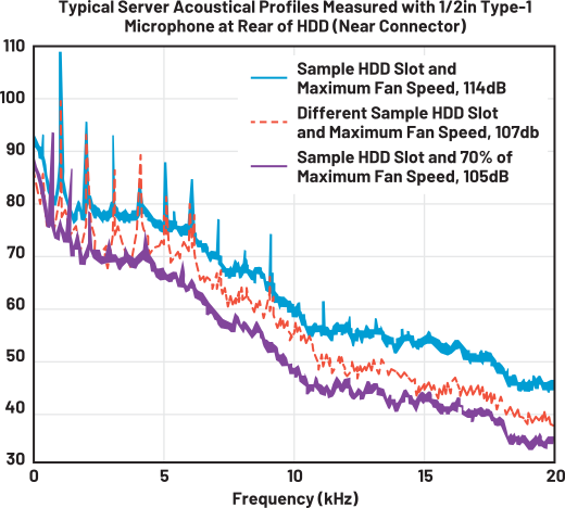
In Figure 1, note the prominent blade-pass harmonics (spikes) and the linear frequency shift as fan speed increases. Sound pressure levels scale at ~50 log (fan speed change), demonstrating why a transition to 100% PWM causes a power-law surge in acoustic energy. The variance between the blue (slot A) and orange (slot B) curves highlights that acoustic signatures are slot dependent, necessitating a system-wide safe-capped PWM threshold to protect the most sensitive drive locations.1
As outlined in Table 1, neither controller offers a complete outof-the-box solution for this design: the MAX31760 lacks BMC hang detection, while the MAX31790 lacks a programmable safe-speed cap. Therefore, the technical challenge is to implement a solution that combines the watchdog detection of the MAX31790 with the safe-speed capping capabilities of the MAX31760.
| Feature | MAX31790 | MAX31760 |
| Number of Channels | Six independent channels | Single channel (main) |
| I2C Watchdog Timer | Integrated, detects BMC inactivity | None, cannot detect BMC hang |
| Fault State Output | Hardwired to 100% PWM | Programmable safe NVM-capped speed |
| PWM Output Architecture | Open-drain | Open-drain |
Solution A: Dual-Chip Hardware Override (MAX31790)
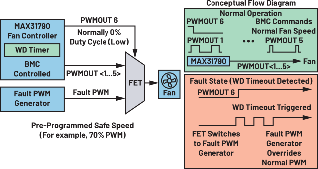
The architecture in Figure 2 maintains the MAX31790 as the primary controller but uses an external fault PWM generator to provide a safe signal (for example, 60% to 70% PWM) during a timeout.
The PWMOUT6 Trigger Logic
In this design, the primary controller’s PWMOUT6 is repurposed as a hardware control signal rather than a fan driver. This allows the system to use the MAX31790’s internal watchdog to physically toggle between two signal sources.
- Normal Operation: The BMC maintains PWMOUT6 at a 0% duty cycle (logic low). This state keeps the hardware switch in its default position, allowing the primary PWM lines to drive the fans.
- Fault State: Upon a watchdog (WD) timeout (programmable), the MAX31790 internal logic forces all channels, including PWMOUT6, to 100% (logic high). This transition can be used as a switch.
- Hardware Toggle: The transition of PWMOUT6 to high triggers an external MOSFET-based switch to disconnect the primary PWM lines and connect the output of the fault PWM generator.
Designing the Switch: Open-Drain vs. Push-Pull
The implementation of this MOSFET switch is not universal; it must be tailored to the output stage of the specific fault generator IC selected for the backup role. The goal is to ensure the backup signal never leaks into the primary control line while the BMC is healthy.
- Open-Drain Architecture (MAX31790, MAX31760): Since these ICs only pull to ground, a single N-channel MOSFET (for example, the NX3020NAKS-Q) is sufficient. When the gate is pulled low by PWMOUT6 (normal state), the fault IC is isolated. Because the output is open-drain, it remains floating and does not interfere with the primary signal.
- Push-Pull Architecture (MAX31740, DS1050): These ICs actively drive the line to VDD. An NMOS contains an internal body diode that could be forward-biased by the fault IC’s active-high signal, causing leakage into the fan line during normal operation. To prevent this, a back-to-back FET configuration (for example, the SSM5N16FU) is mandatory to provide absolute isolation in both directions.
Solution B: Simulated Watchdog Workaround (MAX31760)
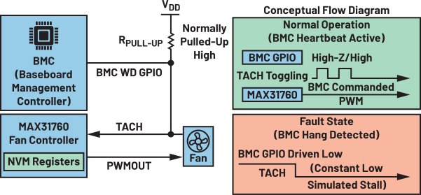
The MAX31760 is often preferred because its NVM allows the fault speed to be precisely capped (for example, 60% to 70% PWM). To address its lack of a watchdog timer, a simulated WD is implemented via hardware. See Figure 3.
Implementation Logic
- Hardware Link: A BMC GPIO is connected to the TACH input pin of the MAX31760.
- Normal Operation: The BMC is programmed to keep the GPIO in a high-impedance (high-Z) or high state. Because the TACH line is typically pulled up to VDD, this allows the MAX31760 to read the actual toggling TACH signal from the fan without interference.
- Failure Detection: If the BMC hangs, the firmware task maintaining the GPIO in high-Z fails. The BMC’s internal GPIO watchdog function then activates, overriding the pin and actively driving the GPIO low. This pulls the TACH line to ground, simulating a fan stall for the MAX31760.
- The Trigger: The MAX31760 detects a stalled fan fault (after three missed TACH pulses).
- Safe State: The MAX31760 automatically reverts to the duty cycle stored in its fault register (NVM). This ensures the fans stay at a safe, non-hazardous speed without BMC intervention.
- It is critical to note that for the simulated watchdog to function, the respective TACH input being used as the BMC’s heartbeat must be enabled. If the TACH input is disabled, the device will not monitor the fault.
When the BMC comes back to life and the fault is cleared, the device handles the return to normal state in one of two ways based on how the fan failure (FF) mode bit is set.
- Fault Indicator Mode (Automatic Recovery): If the FF mode is configured as a fault indicator, the PWM output is tied directly to the real-time status of the fan health. As soon as the BMC GPIO goes high and the MAX31760 detects valid TACH pulses again, the fault condition is considered cleared by the hardware. The device will automatically resume normal operation and revert to the BMC-commanded duty cycle without further intervention.
- Interrupt Mode (Latching Fault): If the FF mode is configured as an interrupt, the fan fault behaves as a latched event. Even after the TACH signal returns to normal, the MAX31760 will remain locked in its NVM-capped safety speed. In this mode, the system will not automatically resume normal operation. To exit this state, one of two manual clear methods must be used.
- I2C Register Reset: The recovered BMC must explicitly write to the MAX31760 to clear the status register bits. Only after this I2C transaction will the PWM output release the safety cap.
- Power-On Reset (POR): A full power cycle of the MAX31760 clears the volatile fault latches, returning the device to its default boot-up state and allowing the BMC to regain control.
Conclusion
The prevention of uncontrolled 100% PWM output is not merely a niche requirement for storage servers; it is a fundamental design principle for any system where high-velocity airflow or mechanical vibration can compromise sensitive components. By implementing the MAX31790 dual-chip override or the MAX31760 simulated watchdog, engineers can decouple thermal safety from mechanical hazards.
While this article primarily addresses the preservation of HDD integrity via TMR mitigation, these architectures apply broadly to any vibration or acoustic-sensitive system. By preventing a transition to 100% PWM, these designs mitigate the extreme acoustic and mechanical energy that can disrupt high-sensitivity equipment.
Ultimately, by matching the MOSFET switching architecture (single NMOS for open-drain or back-to-back FETs for push-pull) to the fault generator’s drive stage, engineers can ensure their systems remain in a stable limp-home mode rather than a hazardous maximum-output state when the primary controller fails.
Reference
1“Hard Disk Drive Performance Degradation Susceptibility to Acoustics.” ASHRAE Technical Committee, 2019.