摘要
Typical IC (integrated circuit) specifications are more important than minimum and maximum specs when optimizing battery life.
Introduction
A similar version of this article appeared in the April 15, 2002 issue of Planet Analog magazine.
Many engineers would not think of using "typical" IC specifications in power-supply designs. Yet typical specs can actually be very useful, sometimes critical, when trying to optimize battery life. By keeping a clear view of design goals and considering how data sheet limits are set, typical specs offer guidance that is sometimes missing from the minimum and maximum limits.
IC production methods continually evolve. Longtime analog system designers have probably noticed that today fewer analog parts have A, B, and C grades. Most power devices have just one grade. Silicon has become more economical as wafer diameters grow and transistor dimensions shrink, but testing has remained relatively costly. Relentless price pressure forces more focused testing and less critical parameters are given "by design" guarantees. The good news is that this has not reduced product quality. Quite the contrary, today's IC manufacturing flows generate far fewer out-of-spec parts than in previous times when "binning" was often a crutch for loose processes. Today there are larger safety margins between on-the-bench typical performance and min/max specifications. In most cases it is hard to argue that this margin is not a benefit. When designing for battery life, however, conservative min/max IC limits can be misleading.
Battery life has the most value as a "typical" parameter (except in medical or other critical uses). Admittedly, operating times quoted for consumer products can be described as optimistic. Nonetheless, a guaranteed limit serves no purpose if the quoted operating time is only a fraction of the real performance. Adding up an IC's maximum operating currents generates mostly useless battery-life numbers. Instead, typical parameters provide more valid results, particularly data from typical operating curves and graphs, as well as typical specs from the spec table.
The typical quiescent current can provide a clue about how much power the IC draws. As an example, the battery life in a cell phone depends largely on quiescent current because a cell phone is on standby for a large percentage of time. Also, the typical shutdown current provides information about the power needed when an IC is in shutdown mode.
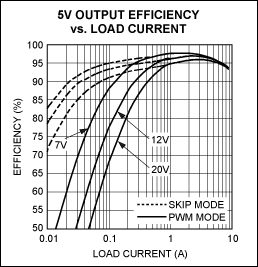
Other considerations include the IC efficiency during operating mode. To extend the battery life, one must minimize the power dissipation. The higher the efficiency, the less power is wasted. Hence, a switching regulator's data sheet includes efficiency curves to help designers extend battery life, especially in portable battery-powered applications. Switching regulators are attractive choices for portable applications because the capacitors and inductors are used to store energy and convert the voltage. One must be careful, however, to find the most efficient "spot" on the IC's efficiency curve for the system design.
For switching regulators, the efficiency curve seen in Figure 1 is important to designers. The typical operating efficiency can help to determine the optimal VIN, ILOAD, and PWM or skip mode, which will in turn ensure that a device achieves the best efficiency and extends battery life.

Figure 1. Typical operating efficiency curve for the MAX17031 step-down controller.
For linear regulators, the dropout voltage represents how much power is dissipated, or wasted. In a linear regulator, IOUT is approximately equal to IIN. Power dissipation is:
VDROPOUT × IOUT ≈ power dissipated
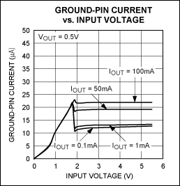
Ground-pin current as in Figure 2 also consumes power in a portable battery-powered application. Ground-pin current is power that is not delivered to the load, so the power is wasted. Selecting the optimal input voltage to achieve the lowest ground-pin current also helps to extend battery life.

Figure 2. Typical operating curve for MAX16999 linear regulator.
The last important step is to understand the system's power profile in each operating state (i.e., off, sleep, run, etc.), and then determine how much time is spent in each state. This is an important exercise because it reveals where most of the energy is going, and where to apply power-supply design effort and BOM cost. If your product spends most of its time off but still biases low-power circuitry in the off state, then money spent on high power efficiency might be wasted. Instead, concentrate on low-load efficiency and low quiescent operating current to optimize the performance where most battery energy is used. Conversely a product with a real hardware ON/OFF switch, that disconnects the battery, should be designed for peak efficiency at the typical operating load current, not the peak. Of course, you still need to consider the maximum loads to ensure that the power supply can supply peak load when needed. The typical numbers will be the best guide to help place the efficiency "sweet spot" where it is needed most.


