摘要
This application note provides an example schematic and software for using the DS1305 real-time clock (RTC) with a PIC microcontroller. The DS1305 is connected to the PIC using the SPI interface. A serial RS-232 port is used for data input and output.
Pin Configuration
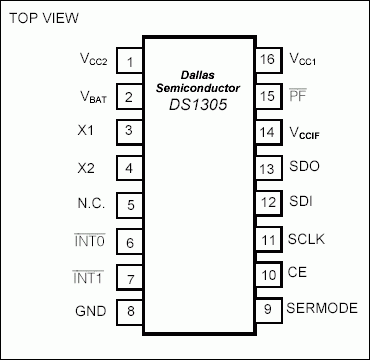
Description
The DS1305real-time clock (RTC) can be interfaced with a microcontroller (µC) using a 3-wire or an SPI™ interface. This application note shows how to connect a DS1305 to a PIC16F628µC. The DS1306 could also be used in this application.
The circuit uses a serial interface for communications. A terminal program with user control of the RS232 DTR control line is required. DTR is used to reset the µC and start code execution. A DS232 is used to perform TTL/RS232 level translation.
A schematic of the circuit is shown in Figures 1 and 2. The software is shown in Figure 3.
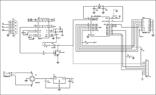
Figure 1. PIC16F628 interface.
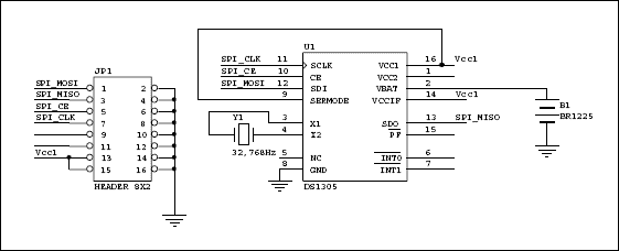
Figure 2. DS1305 daughter card.
Figure 3. Code for Demo
#include <P16F628.inc>
list p=16F628
__config H'3F2A'
; this config gives us LVP and enables /MCLR
errorlevel -302 ; don't print message for operands that are not in bank 0
; define the baud rate for the hardware uart
#define BAUD_VALUE 0x15 ; 0x15 sets the baud rate to 57600 with a 20.0MHz
crystal
#define SPI_CLK PORTA,1 ; spi bus clock line
#define SPI_MOSI PORTA,2 ; spi master out data
#define SPI_MISO PORTA,3 ; spi slave input data
#define SPI_CE PORTA,4 ; chip enable for SPI device
SCRATCH equ 0x40 ; 1 by general purpose scratchpad
TMP equ 0x41 ; temp register
TMP2 equ 0x42 ; temp register
COUNT equ 0x43
YRS equ 0x44
MON equ 0x45
DOW equ 0x46
DAYS equ 0x47
HRS equ 0x48
MINS equ 0x49
SECS equ 0x4a
user_bits equ 0x2C ; this is 0x0C for the 16F84
save_w equ 0x38
save_status equ 0x39
SET_BANK0 MACRO
bcf STATUS, RP0
bcf STATUS, RP1
ENDM
SET_BANK1 MACRO
bsf STATUS, RP0
bcf STATUS, RP1
ENDM
org 0x00
RESET:
goto START
;-----------------------------------------
;--------------- start ---------------
;-----------------------------------------
org 0x0A
START:
; turn off the comparator for porta
SET_BANK0
movlw 0x07
movwf CMCON
; turn off the voltage reference module
SET_BANK1
movlw 0x00
movwf VRCON
SET_BANK0
clrf PORTA ; initialize PORTA
movlw 0x08 ; RA3 read (high-z)
SET_BANK1
movwf TRISA ; set pins for input or output
bsf OPTION_REG, 7 ; turn weak pull-ups on all inputs
SET_BANK0
movlw 0x07 ; Initialize CMCON
movwf CMCON
call uart_init
CheckForCommands:
movlw banner-1 ; move label address into W register
call write ; print string starting at address of label
call uart_getchar ; returns character in W
call uart_putchar ; echo
movwf TMP
bcf TMP,5 ; convert to upper case
movf TMP,W ; put back in W
xorlw 'S' ; write to RTC
btfss STATUS,Z
goto not_ss
call set_clock ; set the clock using data from user
goto CheckForCommands
not_ss:
movf TMP,W ; retrieve character
xorlw 'R' ; read from RTC
btfss STATUS,Z
goto not_rr
call read_clock ; display time and date via serial port
goto CheckForCommands
not_rr:
goto CheckForCommands
;-----------------------------------------
;--- uart routines ---
;-----------------------------------------
;---- send a byte through the serial port ----
uart_putchar:
charwait1:
btfss PIR1, TXIF
goto charwait1
movwf TXREG
return
;---- get a byte from the serial port ----
uart_getchar:
charwait2:
btfss PIR1, RCIF ; is data avalible?
goto charwait2 ; if not then wait
movfw RCREG
return
;----- initialize the serial port -----
uart_init:
SET_BANK1
movlw BAUD_VALUE ; set the baud rate
movwf SPBRG ; mov baudreg into SPBRG, set baud rate
bcf TXSTA, SYNC ; clear SYNC bit, asynchronous mode
bsf TXSTA, BRGH ; BRGH=1, high speed SP mode.
bsf TXSTA, TXEN ; enable transmission
bcf PIE1, RCIE ; disable serial port interrupt
SET_BANK0
bsf RCSTA, SPEN ; set SPEN bit, serial port enable
bsf RCSTA, CREN ; set CREN bit, serial port receive enable
return ; return
;----------------------------------------
;-- text strings for user interface --
;----------------------------------------
banner:
dt "\n\rDS1305 SPI DEMO\n\rR)ead time S)et time\n\r",0h
year:
dt "\n\rYear (0-99): ",0h
month:
dt "Month (1-12): ",0h
dow:
dt "Day of Week (1-7): ",0h
date:
dt "Date (1-28,29,30,31): ",0h
hour:
dt "Hour (0-23): ",0h
minute:
dt "Minute (0-59): ",0h
second:
dt "Second (0-59): ",0h
;-----------------------------------------
;-- character conversion routines --
;-----------------------------------------
;--------- ascii to bcd ----------
readbcd:
clrf TMP ; clear temp reg
gobcd:
call uart_getchar ; returns character in W
call uart_putchar ; echo to screen
xorlw 0dh ; if cr, Z will be set
btfss STATUS,Z ; skip if clear
goto bcd ; go to bcd if Z=0
movf TMP,W ; done, move final value to W
return ; and return
bcd:
xorlw 0dh ; restore value
addlw -30h ; subtract ascii offset
btfsc W,4 ; jump if not A-F
addlw -7 ; if A-F, subtract 7
digit:
andlw 0x0f ; clear upper nibble
bcf TMP,4 ; clear upper nibble of temp reg
bcf TMP,5
bcf TMP,6
bcf TMP,7
movwf SCRATCH ; save W
movf TMP,W ; copy TMP to W
movwf TMP2 ; save TMP
movf SCRATCH,W ; restore W
movwf TMP ; TMP now has org W value
movf TMP2,W ; W now has org TMP value
swapf TMP2,W ; swap nibbles
iorwf TMP,W ; insert bits 0-3 of TMP to W
movwf TMP ; move W into temp reg
goto gobcd ; continue until CR is encountered
;-- convert bcd to ascii --
;-- entry: W=bcd value exit: W=last ascii --
writebcd:
movwf TMP ; save W
swapf TMP,W ; swap nibbles
andlw 0x0f ; clear bits 4-7
addlw 0x06 ; add 6
btfss STATUS,DC ; if a-f, DC=1
goto lessnine ; if DC=0, < 9, so goto lessnine
addlw 0x31 ; add 31h to make ascii
goto digit1 ; skip to output
lessnine:
addlw 0x2a ; add offset for 0-9 to make ascii
digit1:
call uart_putchar ; print char
movf TMP,W ; restore W
andlw 0x0f ; clear bits 4-7
addlw 0x06 ; add 6
btfss STATUS,DC ; if a-f, DC=1
goto lessnine2 ; if DC=0, < 9, so goto lessnine
addlw 0x31 ; add 31h to make ascii
goto digit2 ; skip to output
lessnine2:
addlw 0x2a ; add offset for 0-9 to make ascii
digit2:
call uart_putchar ; print char
return
;---------------------------------------------
;-- display RTC data --
;---------------------------------------------
read_clock:
call RTC_brst_rd ; get the data from the RTC
read_regs:
movf YRS,W
call writebcd
movlw '/'
call uart_putchar
movf MON,W
call writebcd
movlw '/'
call uart_putchar
movf DAYS,W
call writebcd
movlw ' '
call uart_putchar
movf DOW,W
call writebcd
movlw ' '
call uart_putchar
movf HRS,W
call writebcd
movlw ':'
call uart_putchar
movf MINS,W
call writebcd
movlw ':'
call uart_putchar
movf SECS,W
call writebcd
movlw 0x0d ; cr
call uart_putchar
return
;---------------------------------------------
;-- write to the RTC with user-entered data --
;---------------------------------------------
set_clock:
movlw year-1 ; prompt user for data (year)
call write
call readbcd ; get the data
movwf YRS ; save it
movlw month-1 ; prompt user for data (month)
call write
call readbcd
movwf MON
movlw date-1 ; prompt user for data (month)
call write
call readbcd
movwf DAYS
movlw dow-1 ; prompt user for data (month)
call write
call readbcd
movwf DOW
movlw hour-1 ; prompt user for data (month)
call write
call readbcd
movwf HRS
movlw minute-1 ; prompt user for data (month)
call write
call readbcd
movwf MINS
movlw second-1 ; prompt user for data (month)
call write
call readbcd
movwf SECS
call RTC_brst_wr ; now write data to RTC
return
;-----------------------------------------
;-- RTC routines --
;-----------------------------------------
RTC_brst_rd:
bsf SPI_CLK ; assert SCLK for CPOL=1
bsf SPI_CE ; assert CE
movlw 0h ; seconds register read address
call write_RTC ; send the address
call read_RTC ; read the seconds data
movwf SECS ; save it
call read_RTC ; and so on
movwf MINS
call read_RTC
movwf HRS
call read_RTC
movwf DOW
call read_RTC
movwf DAYS
call read_RTC
movwf MON
call read_RTC
movwf YRS
bcf SPI_CE ; de-assert CE
return
RTC_brst_wr:
bsf SPI_CLK ; assert SCLK for CPOL=1
bsf SPI_CE ; assert CE
movlw 08fh ; control register write address
call write_RTC
movlw 0 ; clear write protect
call write_RTC
bcf SPI_CE ; de-assert CE
bsf SPI_CLK ; assert SCLK for CPOL=1
bsf SPI_CE ; assert CE
movlw 08fh ; control register write address
call write_RTC
movlw 0 ; enable osc, disable interrupts
call write_RTC
bcf SPI_CE ; de-assert CE
bsf SPI_CLK ; assert SCLK for CPOL=1
bsf SPI_CE ; assert CE
movlw 80h ; send seconds register write address
call write_RTC
movf SECS, W
call write_RTC
movf MINS, W
call write_RTC
movf HRS, W
call write_RTC
movf DOW, W
call write_RTC
movf DAYS, W
call write_RTC
movf MON, W
call write_RTC
movf YRS, W
call write_RTC
bcf SPI_CE ; de-assert CE
return
;---- Read RTC into W (assume address already sent) ----
;---- assumes CE is asserted ----
read_RTC:
movlw 08h ;Send 8 bits
movwf COUNT
SPI_read_loop:
rlf TMP, 1
bcf SPI_CLK ; clock data out
bcf TMP, 0 ; assume data out is low
btfsc SPI_MISO
bsf TMP, 0 ; if data out=1, set bit
bsf SPI_CLK
decfsz COUNT, 1
goto SPI_read_loop
movf TMP, W
return
;--- Write the byte in W to RTC ---
;---- assumes CE is asserted ----
write_RTC:
movwf TMP ;Save the data
;
;--- Do a SPI bus write of byte in 'TMP' ---
;
SPI_write:
movlw 08h ;Send 8 bits
movwf COUNT
SPI_w_loop:
bcf SPI_CLK
bcf SPI_MOSI ; assume data out is low
btfsc TMP, 7
bsf SPI_MOSI ; if data out=1, set bit
SPI_w_cont:
rlf TMP, 1
bsf SPI_CLK ; clock it in
decfsz COUNT, 1
goto SPI_w_loop
return
;-----------------------------------------
;-- pclsub used for indirect addressing --
;-----------------------------------------
pclsub:
incf SCRATCH,F ; advance table pointer
movf SCRATCH,W ; move table pointer to W
movwf PCL ; jump to address pointed by PCLATH,W
;----------------------------------------
;-- write a string to USART --
;----------------------------------------
write:
movwf SCRATCH ; FSR = string address
GoWrite:
call pclsub ; advance pointer and read pointed byte
addlw 0h ; if contents are zero, Z will be set
btfsc STATUS,Z ; skip if clear
return ; current character is null: end of string
call uart_putchar ; print one character
goto GoWrite ; loop
END
关联至此文章


