How to Design a Supercapacitor Fast Charger with the MAX17701
摘要
Supercapacitors (also known as ultracapacitors) have high power capability which make them ideal for applications that require short charge and discharge cycles with high current. In this application note, we will show a practical design for an automatic pallet shuttle. In this application, the fast charge can be provided by a flexible, high-efficiency, high-voltage, and high-current charger based on a synchronous, step-down, supercapacitor charger controller.
Introduction
Supercapacitors (also known as ultracapacitors) have unique advantages over other energy storage mediums and are increasingly finding usage in a variety of applications.
Supercapacitors can hold large amount of energy compared to ordinary capacitors. They also have very high power density, allowing large charge and discharge currents relative to batteries. Unlike batteries, supercapacitors work down to 0V and do not suffer from overdischarge. These characteristics make supercapacitors the right choice for applications where rapid charging and discharging is needed. We'll go through a conceptual fast supercapacitor charger design using the MAX17701 for an automatic aisle carrier (or pallet shuttle) in a modern warehouse.
Supercapacitor Characteristics
First, let's examine some of the key characteristics of a supercapacitor. Unlike batteries, supercapacitors function on electrostatic principles with no chemical reactions, avoiding the high internal resistance and lifetime issues associated with chemical storage of batteries.
Supercapacitors are also known as double-layer electrical capacitor (EDLC) that store electrical energy by intercalating charges at the electrode-electrolyte interface forming a double layer of charges, enabling much higher energy storage capability over ordinary capacitors. The primary characteristics of supercapacitors are as follows:
- High power output, capable of rapid charge/discharge with large currents
- Low internal resistance, low losses during charge/discharge
- Full discharge to 0V
- Charge and discharge over several thousand cycles. Lifetime up to 40 years, depending on the operating temperature and applied voltage
An ordinary capacitor usually consists of two metal plates, separated by an insulator (like air or a plastic film). During charging, electrons accumulate on one conductor and depart from the other. One side gains a negative charge while the other side builds a positive. The natural pull of the negative charge towards the positive one creates an electric field through the insulator and the energy is stored.
A supercapacitor also contains two metal plates, only coated with a porous material known as activated carbon. They are immersed in an electrolyte made of positive and negative ions dissolved in a solvent. One plate is positive and the other is negative. The supercapacitor stores electrical energy by intercalating charges at the electrode–electrolyte interface forming the double layer of charges, thus giving it the name, double-layer electrical capacitor. The charges are physically deposited by electrostatic attraction, resulting in rapid charge-discharge kinetics, high-power density, and long-life cycle (as no chemical reaction is involved unlike batteries).1,2
Fast Supercapacitor Charger Design for an Automatic Aisle Carrier
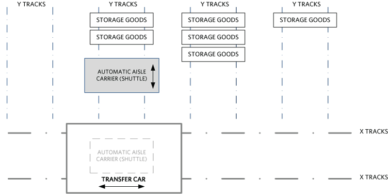
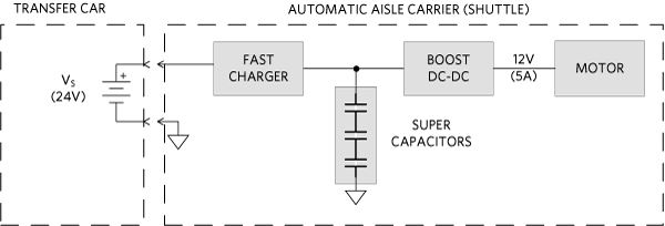
In a modern storage facility consisting of one or more racking units, it is comprised of a high number of channels on various levels that store thousands of pallets. For each level, a transfer car serves the storage channels (X tracks), while a motorized automatic aisle carrier moves inside them (track Y), see Figure 1. The aisle carrier (shuttle) is an ideal application using supercapacitors as the main source of electrical power. The supercapacitors recharge quickly, within seconds, while on board the transfer car. The autonomous shuttle flight within the channel lasts only a few seconds, requiring a limited amount of energy per-flight, supplied by the supercapacitors. The supercapacitors are recharged while the shuttle is docked in the transfer car, which provides 24VDC power source. The shuttle is always available and can operate continuously, 24/7.

Figure 1. Transfer car and aisle carrier (shuttle) in one storage level.
Design specification
Aisle carrier charge/discharge specification:
- Aisle carrier motor (and other circuitry) maximum power requirement, POUT: 12V at 5A
- Aisle carrier maximum operating time in the channel, tC: 5 seconds
- Aisle carrier minimum docking time on transfer car, tD: 10 seconds
- Power source on transfer car, VS: 24VDC ±10%
- Supercapacitor pack, C, life expectancy: > 10 years

Figure 2. Transfer car and aisle carrier power system diagram.
Selecting and Determining the Supercapacitor Operating Range
We'll start with the output power requirement, PO is 12V x 5A = 60W. Allowing 85% boost converter efficiency, we need the input power to the boost converter at 60W/85% = 70.6W. Thus, the energy needed from the supercapacitor module is E = 70.6W x tC = 353J maximum for each shuttle run.
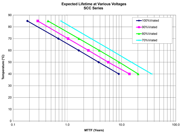
The supercapacitor pack has 3 cells in series, totaling a 9V-rated operating voltage. Allowing a 90% voltage derating for supercapacitor longevity, the maximum charging voltage is 9V x 90% = 8.1V (VMAX). This will give 15 years lifetime for the capacitor pack at 40°C operating temperature, as shown in Figure 3. The supercapacitor pack must have an appropriate cell-balancing circuit to realize the full-voltage derating benefit.

Figure 3. AVX-SCC supercapacitor life expectancy vs. voltage derating and temperature3.
C = 2 x E / (VMAX2 – VMIN2), or C = 2 x 353J / (8.1V2 – 2.7V2) = 12F
Using three SCCV40E506SRB in series at 50F each, this provides 15F. That figure has already taken -10% capacitance initial tolerance into account and provides an additional 25% capacity margin.
Design the Supercapacitor Charger
The charger must charge this 15F supercapacitor from 2.7V to 8.1V in 10 seconds or less. We can calculate the charging current, IC, as follows:
IC = C x dV/dt = 15F x (8.1V - 2.7V)/10s = 8.1A
Pick IC = 10A, allowing enough headroom for charging current and voltage tolerances. It's also worth noting that this 10A current is no way near the current rating of the chosen supercapacitors, which have the peak current limit rating at 37.5A. Low charging current relative to the peak current rating means relatively low internal heating to the capacitors.
Fast Supercapacitors Charger Circuit using MAX17701
The MAX17701 is a high-efficiency, high-voltage Himalaya synchronous, step-down, supercapacitor charger controller designed to operate over an input-voltage range of 4.5V to 60V. The device charges a supercapacitor with a ±4% accurate constant current, which is programmable. After the supercapacitor is charged, the device regulates the no-load output voltage with ±1% accuracy. The output voltage is programmable from 1.25V up to (VDCIN - 2.1V). The MAX17701 is the perfect choice for a fast supercapacitor charger in this application.
Amongst many other features, the MAX17701 also provides a safety timer (TMR) feature to set the maximum-allowed constant current (CC) mode charging time. The device features an uncommitted comparator, which can be used to detect an output overvoltage event (OVI) and prevent the supercapacitor from overcharging. Let's go through some of these features and set them up appropriately to our automatic aisle carrier fast supercapacitor charger design.
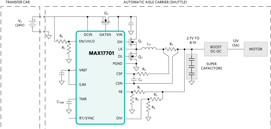
Figure 4 is a simplified schematic of the charger using the MAX17701.

Figure 4. Transfer car and aisle carrier power system diagram calculated parameters.
Switching Frequency Setting
The RT/SYNC is switching frequency programming/synchronization input. We'll leave RT/SYNC open for the default 350kHz frequency. The switching frequency is adjustable from 125kHz to 2.2MHz and can sync with an external clock. Higher switching frequency reduces the output LC filter sizes at the expense of lower efficiency. Refer to the MAX17701 datasheet for more details.
Operating Input Voltage Setting
The input power source is 24VDC ± 10%. Let's give it another 10% headroom, so we will set our charger minimum operating voltage at 19.2V. The EN/UVLO pin is Enable/Undervoltage Lockout Input with the rising threshold of 1.25V. Refer to the Setting the Input Undervoltage-Lockout Level (EN/UVLO) section in the MAX17701 datasheet to calculate the resistor-divider, R6 and R7, values.
CC Mode Charging Current Setting (ILIM)
Refer to the datasheet for a detailed discussion. Let's use (VCSP - VCSN) of 50mV across RS for ±4% charging current accuracy. Our target charging current, ICHGMAX (or IC), is 10A.
RS = (VCSP - VCSN)/I = 50mV/10A = 5mO
VILIM = 30 × RS × ICHGMAX = 30 x 5mO x 10A = 1.5V
This value can be conveniently set by connecting ILIM directly to VREF without using a resistor-divider.
Connect an R-C filter in the current-sense signal path as shown in Figure 3 to attenuate switching noise while preserving accuracy and bandwidth. The R-C filter corner frequency should be 5 times the switching frequency. The recommended filter resistance (R5) is 40O for minimal impact on the current-sense accuracy.
C5 = 1/(2p x R1 x 5 x fSW) = 1/(2p x 40O x 5 x 350kHz) = 2.3nF
Let's use C5 = 2.2nF, it is the closest standard value.
Safety Timer Setting
The safety timer (TMR) feature to set the maximum-allowed constant current (CC) mode charging time. In our application, charging a 15F supercapacitor from 0 to 8.1V at 10A will take approximately 12s. Set tSC_TMR to 18s, allowing 50% margin for timer tolerance and headroom. If charging stays in CC mode for longer than 18s, the charger will turn off and then restart after 4 x tSC_TMR, or 52s later.
Use the following equation to calculate CTMR for the required tSC_TMR:
CTMR = 1.15 × (tSC_TMR/(2 × 32767) - 1.2µ) × 10µA/(1.5V - 0.96V) = 5.8nF;
where:
tSC_TMR = desired safety timer timeout setting in seconds.
CTMR = TMR capacitor in Farads.
Let's use CTMR = 6.8nF, which is the closest standard capacitor value.
Output Regulation Voltage Setting
Refer to Setting the Output Voltage and Voltage Regulation Loop (FB) section in the datasheet to calculate for R1 and R2 values to set our application output voltage regulation to 8.1V nominal.
Output Overvoltage Setting
The overvoltage protection feature can protect the supercapacitor stack from being overcharged. If VOVI exceeds VOVI_TH, charging is stopped, and the charger enters the latched fault. Refer to the datasheet to calculate R3 and R4 values to set the output overvoltage threshold to 9V.
Selecting the Input Short-Circuit Protection MOSFET
The GATEN pin controls the gate of an external nMOSFET connected between the power source, DCIN (VS), and VIN to prevent supercapacitor discharge, if VS is shorted to PGND. Select a power MOSFET for Q3 with 40V rating or more and 20A or more. VISHAY SIR826ADP MOSFET (80V/60A) is more than adequate for this application. This MOSFET has low RDS(ON) which minimizes conduction losses for better efficiency.
Selecting the Switching Power MOSFETs and Output Filter
At 350kHz, input voltage at 24V nominal, and output voltage at 8.1V. The switching duty cycle is approximately 34% at steady-state constant voltage mode, and the top switch on-time is 1µs. Allowing 30% steady-state output current ripple, we need the output filter inductor value to be:
LO = (24V - 8.1V) x 1µs/3.3A = 4.8µH
LO carries the output current of 10A DC maximum, with 3.3A peak-to-peak ripple current. Chose an inductor with adequate current rating. For the switching power MOSFETs, choose VISHAY SIR826ADP (80V/60A) for Q1 and Q2.
Choosing the switching frequency, output filter inductor, and switching power MOSFETs is a balance of solution efficiency, size, and cost. Contact Analog's application engineer at www.analog.com/en/support/technical-support for assistance to create your optimum design, based on your solution preferences.
Conclusion
Supercapacitors have unique advantages over other energy storage mediums and are increasingly finding usage in a variety of applications. Supercapacitors can hold a large amount of energy and have very high-power density, allowing large charge and discharge current. A supercapacitor is the right choice for applications where rapid charging and discharging is needed such as an automatic aisle carrier in a modern warehouse. The MAX17701 is an ideal controller for fast supercapacitor charger designs.
References


