Halve The Jitter With The LTC6957 Filters While Buffering 10MHz
You’re looking for a low additive phase noise (jitter) buffer to distribute the 10MHz sinewave source in your system as a reference clock. After looking at several datasheets from different vendors, you realize that there isn’t much performance information given at this relatively low frequency. Most high-performance clock buffers/distributors on the market seem to be well specified for frequencies much higher than 10MHz. The lab might be the best place to clarify this point, so let’s head there.
Let’s pick the best clock buffer in its class, namely the LTC6957, and connect a 10MHz OCXO to the input of the DC1766A-A, the demo board for the LTC6957-3 with in-phase CMOS outputs, via a step attenuator to control the input’s amplitude. The following figure shows our setup. To evaluate the performance of the part with a 10MHz input sinewave with varied amplitude, let’s measure the phase noise floor of the CMOS output at 100kHz offset from the carrier.

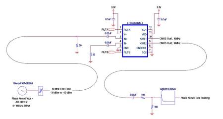
Figure 1. Halve The Jitter With The LTC6957 Filters While Buffering 10MHz.
The OCXO phase noise floor is low compared to that of the LTC6957 and will be ignored in the following analysis. This means that the phase noise measurements taken at the output of the LTC6957 will be assumed to be the additive phase noise of the LTC6957 without incurring much error by doing so. (The Wenzel OCXO used in this experiment burns a whole lot more power and costs significantly more than the LTC6957, so it’s of no surprise that its noise floor is lower.)
The following is the resulting phase noise floor as the amplitude of the input sinewave is varied over the specified input range of the LTC6957.

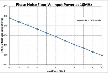
Figure 2. LTC6957 Phase Noise Floor at 10MHz without Engaging its Filters.
The phase noise floor seems to be degrading almost linearly in a 1-to-1 ratio versus the input amplitude (or slew rate). This is expected as the LTC6957 is a limiting amplifier, and every other limiting amplifier or clock buffer/distributor on the market will behave similarly when the input slew rate is relatively low compared to the maximum specified rate.
Just like any other electronic amplifier, a limiting amplifier has broadband noise at its input. The input noise interferes with the sinewave and can randomly change the zero crossing moments from their ideal instants at the limiting amplifier’s input. The noise shifts the location of the zero crossings such that the period of the amplifier output varies from one cycle to another. This creates jitter and degrades the phase noise of the signal.
The shorter the incoming signal lingers around the zero-crossing of the limiting amplifier, the less the input noise can affect it. In other words, the faster the slew rate of the input sinewave is, the less jitter is added by the limiting amplifier’s input stage.
Now, what every other limiting amplifier or buffer on the market lacks is a way to limit the input broadband noise by limiting the bandwidth of the first stage amplifier inside the amplifier. As we will find out shortly, restraining the bandwidth when the extra bandwidth offers no advantage to the limiting amplifier (which is true when the input frequency is low compared to the amplifier’s bandwidth), will prove crucial in limiting the phase noise degradation of the limiting amplifier. The LTC6957 is very different in this regard as it offers the choice to limit the input bandwidth by offering two filters with different cutoffs and subsequently the option to reduce the input noise when this extra bandwidth is not needed.1
Let’s go back to the lab and repeat our previous measurement while turning on the appropriate LTC6957 filters according to the datasheet recommendation (see the “Input Filtering” section of the LTC6957 datasheet).

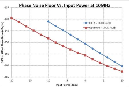
Figure 3. LTC6957 Phase Noise Floor at 10MHz with the Appropriate Filters Engaged.
As we can see, there is up to 7dB of improvement at –10dBm input with the engagement of the LTC6957 filters. That means that with the help of the filters, the jitter is less than half the unfiltered value. Because other vendors do not offer this option of limiting the bandwidth, they cannot limit the influence of their own broadband input noise and hence the jitter degradation occurring at lower input frequencies. The LTC6957 is a higher frequency buffer/limiter, but it also evolves with the use of the filters to excel at lower frequencies.
Given the phase noise performance of the LTC6957 is boosted by engaging the filters, why not try to use the LTC6957 with inputs below the specified –10dBm value? The above measurement shows that lowering the input down to –20dBm seems to still result in a robust behavior with the help of these filters. It should be noted that the design of the LTC6957 can support operation down to –20dBm at 10MHz and the –10dBm specification in the datasheet was driven by ATE limitations. Most parts can do –30dBm, but limiting the low-end to –20dBm leaves margin for temperature and part-to-part variations.
Besides showing the influence of the filters, these measurements also answered the original question about missing 10MHz performance specifications in limiting amplifier datasheets by explicitly presenting the LTC6957 performance at this frequency.
关于作者


