Feature-Rich Battery Charger that Manages Both Battery Charging and Bus Voltage Regulation
Feature-Rich Battery Charger that Manages Both Battery Charging and Bus Voltage Regulation
by
John Shannon
2003-09-01
Introduction
Until now power management in portable devices has required a mix of major components to fulfill the basic functions of battery charging and generation of system supply voltages. A typical solution requires at least two major devices (and associated external components): one charger IC for charging the battery and another IC to supply a regulated system bus voltage from a constantly changing battery voltage. The LTC1980 is a single-device solution that manages both battery charging and generation of the regulated system bus voltage.
Powerful Features
The LTC1980, in simple terms, controls the power flow between the AC adapter, a battery and the system bus. The basic LTC1980 circuit is a synchronous flyback converter. In such a configuration, power can flow either way through the converter, a fact that is exploited to charge or discharge the battery, depending on the power needs of the system.
The battery charger portion of the LTC1980 is a full-featured, constant current, constant voltage, Li-Ion charger with timer termination. The LTC1980 can be set up for either 1- or 2-cell, and 4.1V or 4.2V chemistries. This switch mode charger maintains high efficiency over a wide range of input voltages. The flyback topology allows any input voltage to generate any output voltage, unlike buck or boost topology chargers that require the input voltage to be always higher or always lower than the battery voltage.
Charging (AC Power Present)
If the AC adapter is present and has sufficient voltage then the LTC1980 enters charge mode. In charge mode power flows from the adapter to both the system bus and the battery. The charger uses a constant current, constant voltage algorithm that is suitable for Li-Ion cells. Deeply discharged batteries are trickle charged with a low current until the battery voltage exceeds the trickle charge threshold, at which point full current charging commences. The switch mode operation of the charger typically keeps efficiency above 80%, which results in less heat generation compared to a linear charger. Adapter power also flows directly to the system bus via a linear regulator. The efficiency of the linear converter is simply the ratio of the system bus voltage to the adapter voltage, so losses are minimized if the adapter voltage is close to the desired system bus voltage.

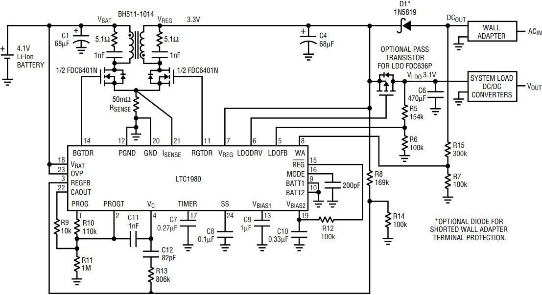
Figure 1. Typical application for single Li-Ion cell.
Discharging (Battery Mode)
When the adapter input falls, so that the system bus voltage requirements can no longer be met, the LTC1980 switches to the regulator mode. In this mode the LTC1980 no longer functions as a battery charger. It instead acts as a battery discharger. Power flows “backwards” from the battery to the linear regulator. The output voltage of the flyback, which is input to the linear regulator, should be as low as possible in order to maximize efficiency and battery run time. The efficiency of the battery to system bus voltage conversion can be as high as 88%.
The Linear Regulator
A low dropout regulator, using an external P-FET as the pass element, regulates the system bus voltage. The linear regulator takes its power from the output of the AC adapter. Dissipation in the linear regulator is lowest when the AC adapter voltage is near the system bus voltage. When the system is in battery discharging mode, the voltage input to the linear regulator is the output of the synchronous flyback converter. This voltage should be set to be only a percent or two above the required output voltage (allowing for IR drops in the pass element). This prevents saturating the gate drive to the pass element and will aid in transient recovery.
Figure 1 shows a typical application circuit for charging a single 4.1V Li-Ion cell. The adapter voltage can vary from 4V to 9V, demonstrating one key advantage of the flyback topology. Figures 2 and 3 show battery current and adapter voltage during the transition from battery charging (adapter present) to regulator mode (battery discharging). The load on the linear regulator is 200mA, supported either by the battery or the adapter. When the adapter is present the battery is charged at about 650mA. Once the wall adapter is removed the battery is discharged as power flows back through the synchronous flyback converter to support the 200mA load on the linear regulator.

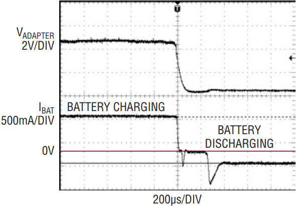
Figure 2. Adapter voltage and battery current (adapter removal).

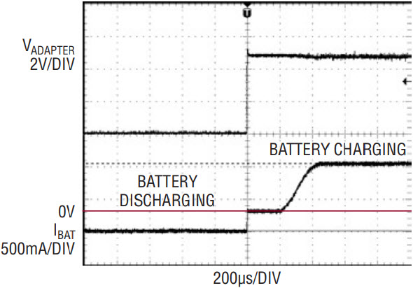
Figure 3. Adapter voltage and battery current (adapter insertion).
Conclusion
The LTC1980 manages both battery charging and system voltage regulation, which is typically the work of two separate devices and their corresponding external circuitry. This feature combined with the fact that the design of the LTC1980 also allows for battery voltages either above or below the adapter voltage, greatly simplifies the task of integrating a battery and adapter into a portable device.
关于作者


