60V Synchronous, Low EMI Buck-Boost for High Power and High Efficiency
Electric vehicle, solar power and industrial power applications place significant power and efficiency demands on DC/DC converters. In these environments, complex electronic controls and displays, battery chargers, and high power electric motors operate from wide-ranging battery voltages, various battery chemistries and solar panels. DC/DC regulators must be able to both step-up, and step-down their input voltages. Likewise, loosely regulated high voltage industrial power systems require well regulated high voltage and high current buck-boost bus power. The single-inductor 4-switch buck-boost DC/DC converter excels in these areas, with its easy to use, efficient and rugged structure.

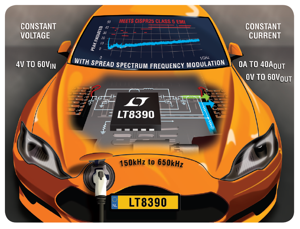
The LT8390 is a synchronous 4-switch buck-boost DC/DC controller that solves many of the issues found in automotive, solar and industrial solutions. Its wide 4V-to-60V operating range can handle high voltage and low voltage automotive transients or the wide-ranging outputs of solar panels. It is ideal for high power 12V and 24V systems, but can regulate an output anywhere between 0V and 60V.
| LT8390 | LT3790 | LTC3789 | LT8705 | |
| Control scheme | Peak-Buck Peak-Boost |
Valley-Buck Peak-Boost |
Valley-Buck Peak-Boost |
Valley-Buck Peak-Boost |
| SSFM | ✓ | |||
| Integrated bootstrap diode | ✓ | |||
| fS range | 150kHz–650kHz | 200kHz–700kHz | 200kHz–600kHz | 100kHz–400kHz |
| VIN range | 4V–60V | 4.7V–60V | 4V–38V | 2.8V–80V |
| DCM | ✓ | ✓ | ✓ |
Proprietary peak current mode architecture produces smooth transitions between buck and boost operation, provides reverse current protection, and smoothly transitions to DCM operation at light load. The LT8390’s unique architecture, matched with spread spectrum frequency modulation (SSFM) enables low EMI solutions, not typically common in buck-boost converters.
For space-constrained designs, the integrated bootstrap diodes and the tiny 4mm × 5mm QFN package minimize required PCB space. For very high power applications, the LT8390 can be paralleled and can be switched as low as 150kHz.
Compact, Low EMI, 12V, 4A Buck-Boost
Low EMI is a requirement in most automobile electronics. Switching regulator EMI is commonly mitigated with EMI filters and electronic shielding, which add to the cost and size of the regulator. The supply designer can also carefully select the switching frequency to avoid some EMI constraint bands, but this severely limits the power supply designer’s options with respect to efficiency and solution size.
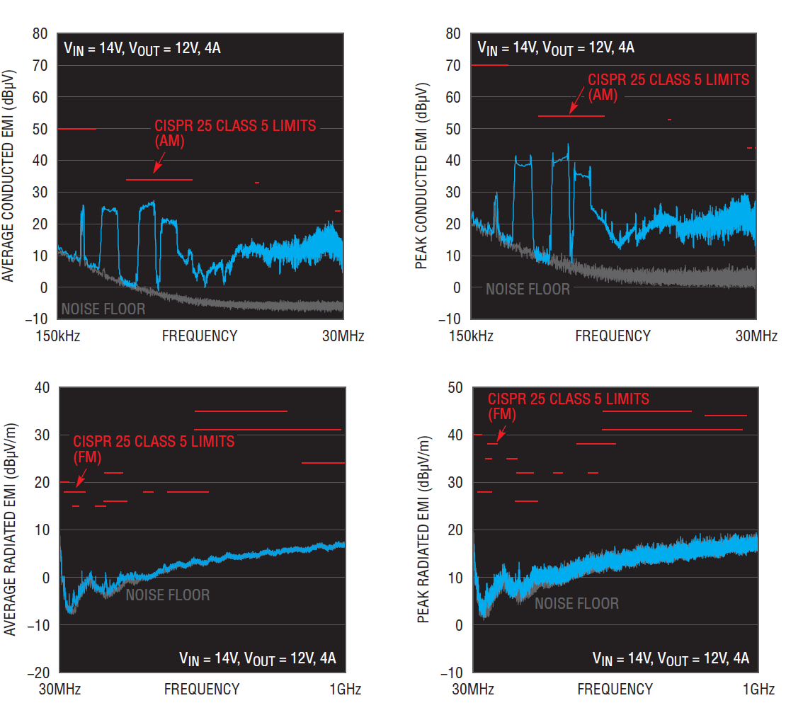
To reduce design time and cost, the LT8390 includes a number of built-in low EMI features, such as SSFM. For instance, with minimal filtering, the powerful 48W converter in Figure 1 passes CISPR 25 Class 5 radiated and conducted EMI (Figure 3). The IC is designed to reduce the complexity of meeting stringent EMI requirements, unique among 4-switch buck-boost controllers.

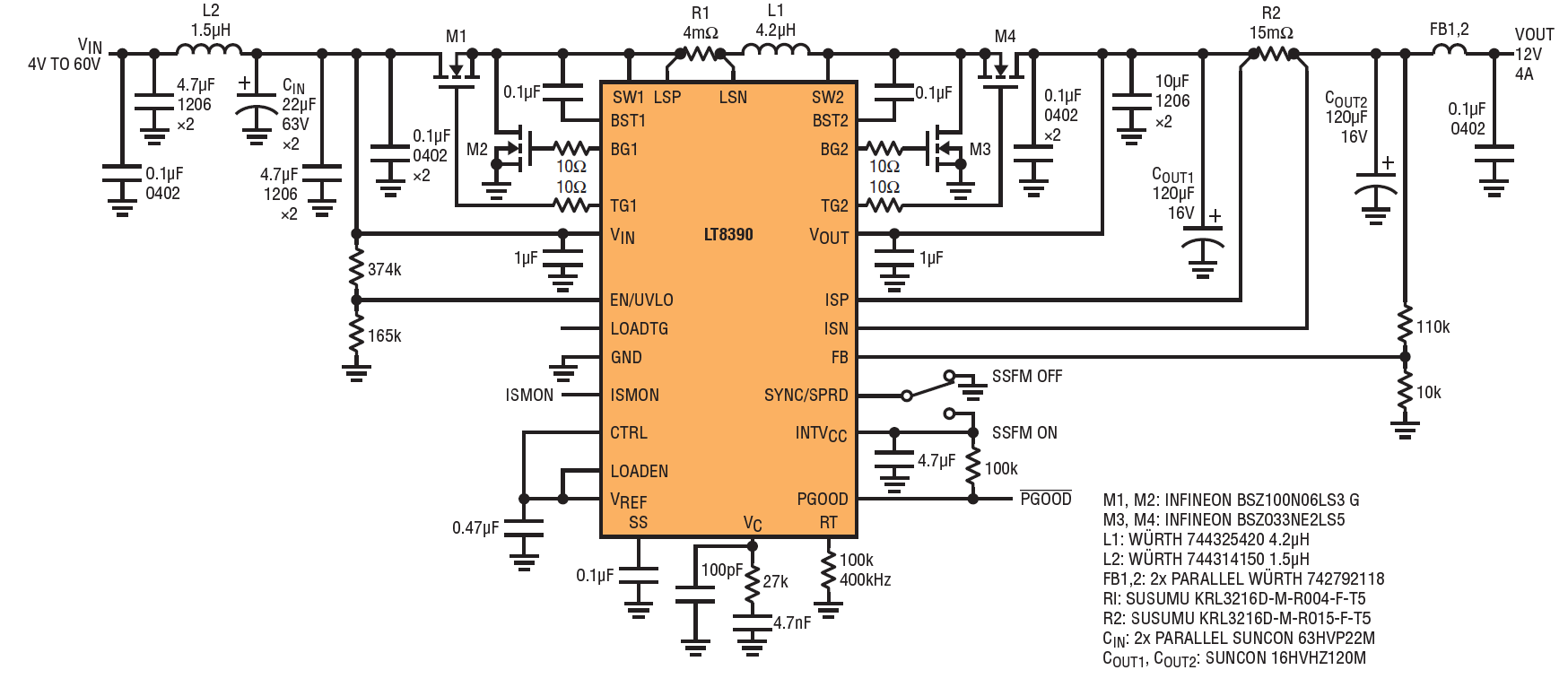
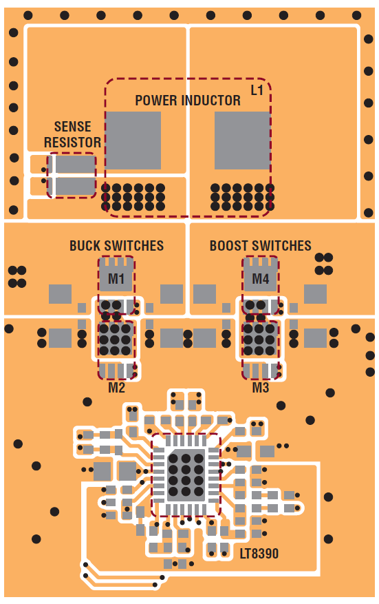
The obvious benefit of SSFM is that it reduces the required size of the input EMI filter in this 400kHz converter. One can see that both the peak and average conducted EMI in the AM band is below the requirement, with only a 1.5μH inductor and a few small ceramic capacitors as the input filter. Compact layout and the use of small 3mm × 3mm MOSFETs minimizes hot-loop size and high frequency radiated EMI (Figure 3). The LT8390 gate drivers are designed for high power, but also low EMI when it is needed. This low EMI 12V regulator is available for testing as a standard demonstration circuit, DC2457A.


The efficiency of the low EMI converter remains high, as shown in Figure 4. It can handle transients up to 60V and down to 4V while maintaining regulation of the 12V output. The 4V operation meets new, low voltage requirements for electric vehicles with energy-saving start-stop requirements and very low voltage transients.


High Power Buck-Boost Single Stage
The LT8390 is capable of producing
very high power operation. In
high power designs, synchronous
switching and 150kHz operation limit switching losses and thermal dissipation. This enables design of very high power and high current converters.
The buck-boost converter shown in Figure 5 is a typical example, supporting VIN = 9V–36V, VOUT = 12V and IOUT = 25A, capability for a 300W power output. At full load, efficiency remains high (Figure 6) in all modes—boost, buck and buck-boost. This enables the LT8390 to regulate under all input conditions without overheating, doing so without the expense of a heat sink or fan. Nevertheless, cooling components can be added to increase power capability.

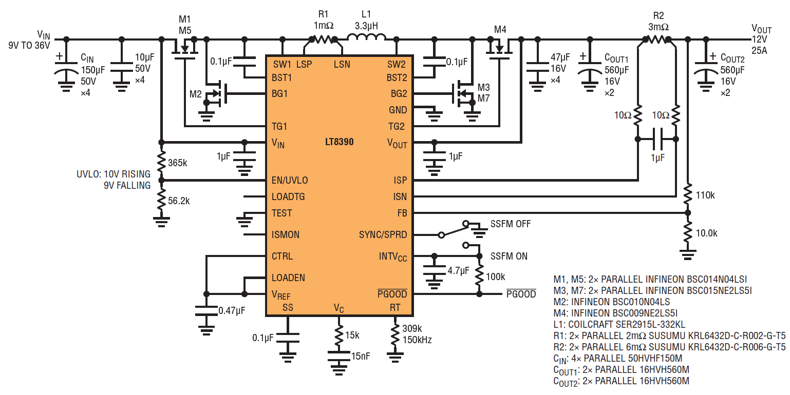


The gate drivers support high power parallel MOSFETs, such as the M1/M5 and M3/M7 pairs designated in Figure 5.
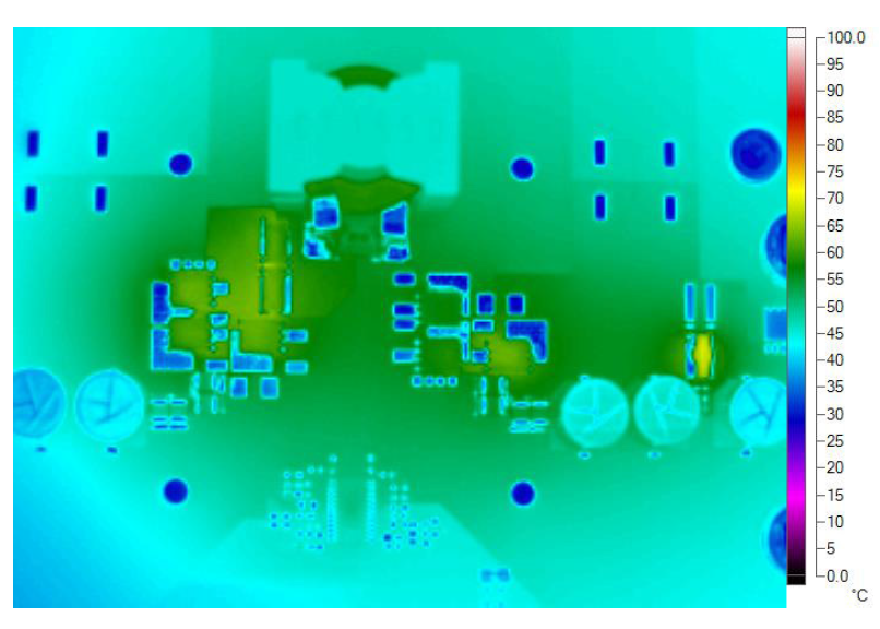
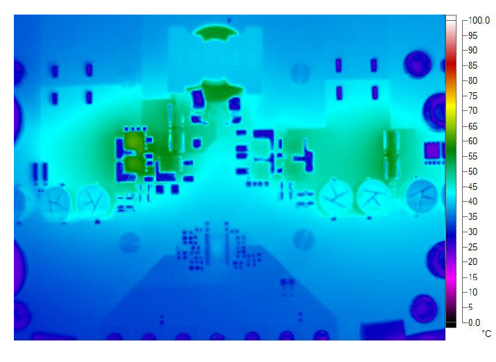
The 300W converter in Figure 5 has excellent thermal performance without the use of a fan or heat sink. With only a standard 4-layer PCB, the 300W converter reaches a worst-case high temperature of 66°C at 12V input as shown in Figure 7. The power MOSFETs remain relatively cool even with the 4-switch operation and high current. Its worst-case thermal condition is at 9.5V input. This is the highest input current and lowest input voltage of the 4-switch buck-boost operation region. At 9.5V input, the hottest component is the power inductor, which remains below 100°C.

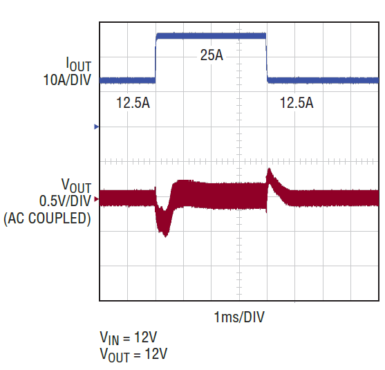
For high efficiency at light load, the LT8390’s proprietary peak current mode buck-boost architecture ensures it runs either in discontinuous conduction mode (DCM) or pulse-skipping mode (PSM) without reversed inductor current. Efficiency over the load range is shown in Figure 8. It can achieve more than 90% efficiency at 0.1% load when VIN = 12V. Figure 9 shows the load transient response at 12V input, 12V output between half load and full load.


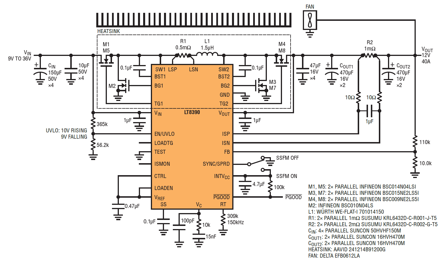
Add a heat sink and a fan to push the output power of LT8390 buck-boost to 12V at 40A, 480W, as shown in Figure 10. The heat sink and fan are attached to the back side of PCB board that features an isolated thermal pad. The fan can be powered by the 12V output. Figure 11 shows the thermal at 12V input, 12V output at 40A. The hottest part is the top MOSFET at 62°C.


Parallel High Power Converter
When thermal performance becomes the limiting factor in creating a high power voltage regulator system, the LT8390 is capable of parallel operation to increase total output power capability while maintaining an acceptable operating temperature over the input voltage range. Even at much higher output power, parallel LT8390 systems exhibit thermal performance similar to a single-phase LT8390 system, since output power and thermal dissipation are split between two converters. Along with improved thermal performance, parallel LT8390 systems are driven out of phase, effectively reducing the output ripple of the system.
The LT8390 has a number of features that enable it to be easily paralleled, including the its ability to operate as both a constant voltage and constant current regulator. This enables a single LT8390 to monitor and regulate the output voltage, while additional LT8390s operate as constant current regulators.
In this master-slave parallel system, the voltage regulator (master) senses the total output current of the system, and scales that current information to that of a single phase to be sent to the current regulators (slaves). Output current information provided at the ISMON pin of the voltage regulator is scaled and buffered inside LT8390 to match the CTRL pin operating voltage range. This allows the current regulator boards to be driven directly by the voltage regulator, ensuring balanced current sharing between phases. LT8390’s ability to share current equally using the ISMON and CTRL pins of the part enables independent optimization of the voltage and current regulators before being combined into a single system.
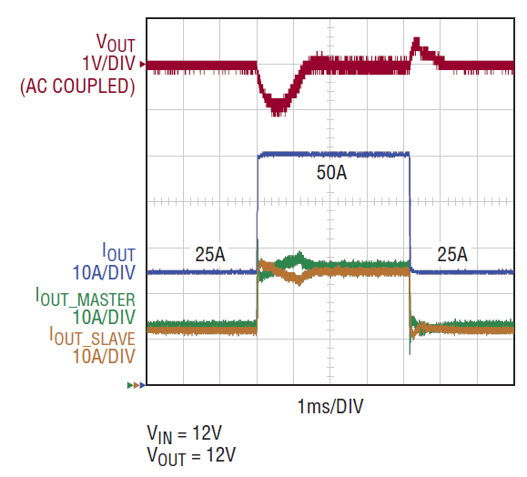
In the example circuit shown in Figure 12, two 300W LT8390 demo circuits are optimized independently: one circuit is set up for constant voltage operation, and the other for constant current at the same output power. The two optimized converters are connected in parallel with the voltage regulator sending its ISMON signal to the current regulator’s CTRL pin. Load sharing is maintained even during transients, as shown in Figure 13.

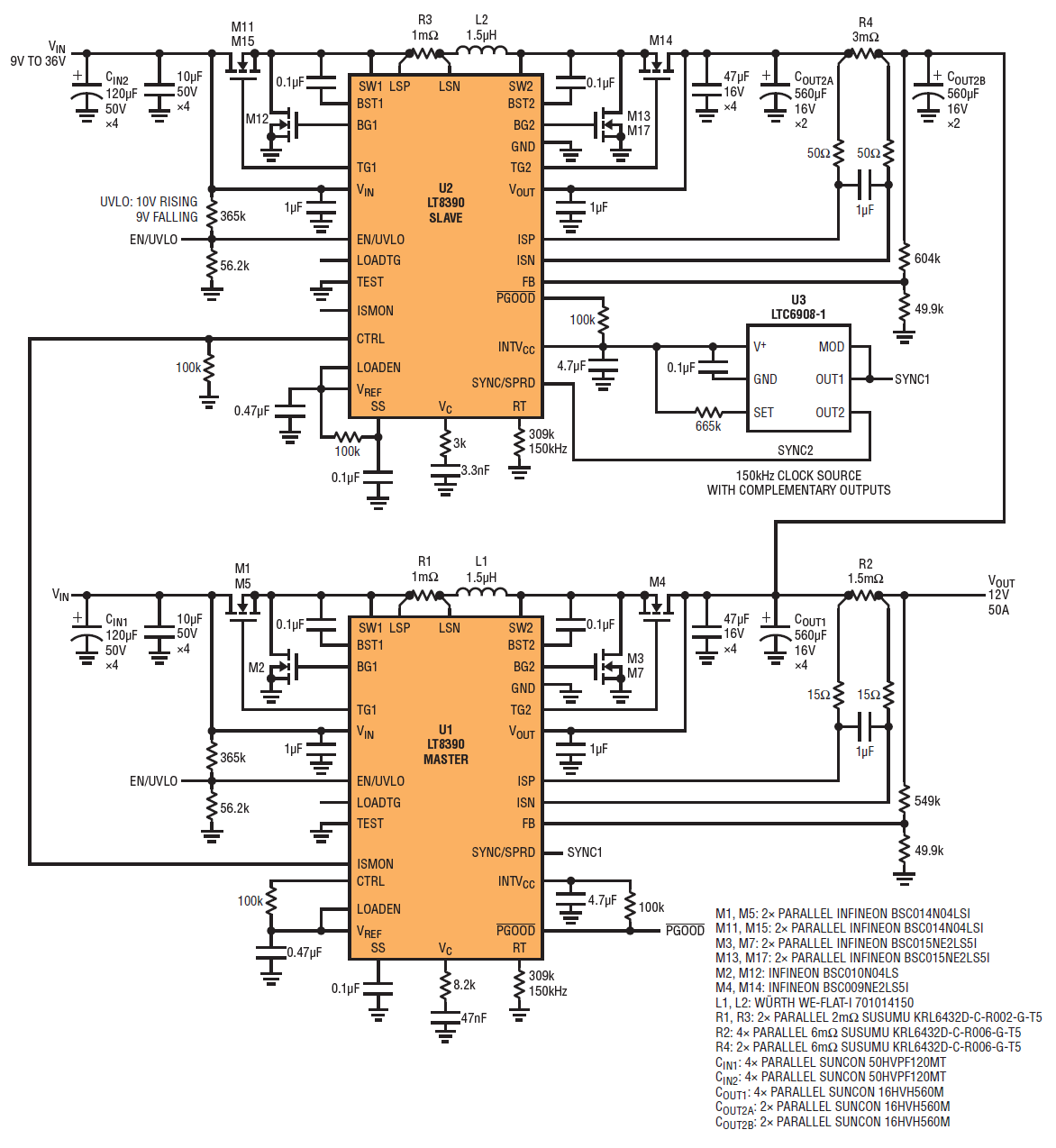

A complementary clock source, such as LTC6908-1, is the only external circuitry needed to complete the parallel system. A final optimization of the combined system’s loop response resulted in a stable parallel system capable of delivering 600W of output power at the same operating temperature as a single 300W LT8390 voltage regulator.
Solar Panel Charger
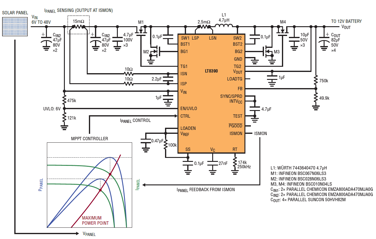
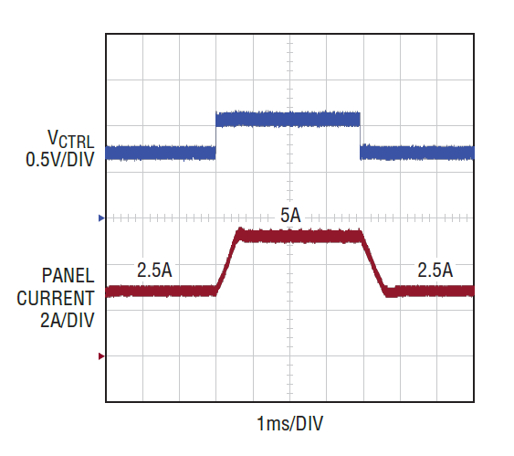
With flexible location current sensing, the LT8390 can regulate input or output current by CTRL voltage. Figure 14 shows a solar panel charger with input current regulation. The input current of the converter, IPANEL, is sensed and sent to the maximum power point tracking (MPPT) controller. With panel voltage and current, the MPPT controller calculates the maximum power point and sends the current command to CTRL for regulation. Figure 15 shows the transient waveform when panel current follows VCTRL command.


Conclusion
The LT8390 4-switch buck-boost controller simplifies the design of demanding industrial and automotive power supply designs. Its application is hardly limited to these areas, as its myriad features—including high efficiency over a wide output load range, low EMI, compact solution size and very high output power capability—are ideal for emerging renewable energy and energy harvesting systems.
关于作者
关联至此文章
产品分类


