MAXREFDES1048


概览
设计资源
描述
The MAX17504 high-efficiency, high-voltage, synchronously rectified step-down converter with dual integrated MOSFETs operates over a 4.5V to 60V input. The converter can deliver up to 3.5A and generates output voltage from 0.9V to 90% VIN. Built-in compensation across the output voltage range eliminates the need for external components. The feedback (FB) regulation is accurate to within ±1.1% over -40°C to +125°C. The devices are available in a compact (5mm x 5mm) TQFN lead (Pb)- free package with an exposed pad. Simulation models are available. The MAX17504 features a peak-current-mode control architecture with a MODE feature that can be used to operate the device in pulse-width modulation (PWM), pulse-frequency modulation (PFM), or discontinuous mode (DCM) control schemes.
PWM operation provides constant frequency operation at all loads and is useful in applications sensitive to switching frequency. PFM operation disables negative inductor current and skips pulses at light loads for high efficiency, allowing the DCM to feature constant frequency operation down to lighter loads than PFM mode. A programmable soft-start feature allows users to reduce input inrush current. The device also incorporates an output enable/ undervoltage lockout pin (EN/UVLO) that allows the user to turn on the part at the desired input voltage level. An open-drain RESET pin provides a delayed power-good signal to the system upon achieving successful regulation of the output voltage.
优势和特点
- Eliminates External Components and Reduces Total Cost
- Reduces Number of DC-DC Regulators to Stock
- Reduces Power Dissipation
- Operates Reliably
所用产品
详情
The MAX17504 high-efficiency, high-voltage, synchronously rectified step-down converter with dual integrated MOSFETs operates over a 4.5V to 60V input. The converter can deliver up to 3.5A and generates output voltage from 0.9V to 90% VIN. Built-in compensation across the output voltage range eliminates the need for external components. The feedback (FB) regulation is accurate to within ±1.1% over -40°C to +125°C. The devices are available in a compact (5mm × 5mm) TQFN lead (Pb)- free package with an exposed pad. Simulation models are available. The MAX17504 features a peak-current-mode control architecture with a MODE feature that can be used to operate the device in pulse-width modulation (PWM), pulse-frequency modulation (PFM), or discontinuous mode (DCM) control schemes.
PWM operation provides constant frequency operation at all loads and is useful in applications sensitive to switching frequency. PFM operation disables negative inductor current and skips pulses at light loads for high efficiency, allowing the DCM to feature constant frequency operation down to lighter loads than PFM mode. A programmable soft-start feature allows users to reduce input inrush current. The device also incorporates an output enable/ undervoltage lockout pin (EN/UVLO) that allows the user to turn on the part at the desired input voltage level. An open-drain RESET pin provides a delayed power-good signal to the system upon achieving successful regulation of the output voltage.
Key benefits and features include the following:
- Eliminates External Components and Reduces Total Cost
- Reduces Number of DC-DC Regulators to Stock
- Reduces Power Dissipation
- Operates Reliably
A small size, high-efficiency buck converter using the MAX17504 is demonstrated for a 3.3V/3A application.
Table 1 provides an overview of the design specification.
| Parameter | Symbol | Min | Max |
| Input Voltage | VIN | 18 | 36 |
| Frequency | fSW | 500kHz | |
| Maximum Efficiency | η | 88% | |
| Output Voltage | VOUT | 3.3V | |
| Load Step | ISTEP | 1.5A | |
| Transient Deviation | ∆VOUT | 150mV | |
| Output Current | IOUT | 0A | 3A |
| Output Power | POUT | 9.9W | |
This document describes the hardware shown in Figure 1. It provides a detailed systematic technical guide to design in a high-efficiency buck converter using the MAX17504 step-down DC-DC converter. The power supply has been built and tested, details of which follow later in this document.


In today’s low-voltage, high-current applications, synchronous buck converters can be much more efficient than conventional buck converters because synchronous converters use MOSFETs, rather than conventional catch diodes. As a result, the power they dissipate in off-periods is reduced significantly. In a steady state, the low-side MOSFET is driven to complement the high-side MOSFET. In other words, whenever one of these switches is on, the other is off. In steady-state conditions, the complementary switching of high-side and low-side MOSFETs regulates VOUT to its set value.
Figure 2 is a simple circuit diagram that illustrates the basic operation of a synchronous buck converter. The main operation depends on the current in the inductor operated through the S1 main switch (generally a MOSFET) and the S2 secondary switch. Initially, when S1 is in the on-state and S2 is in the off-state, the current starts flowing from the source through S1, the inductor, and then to the load. The operation time of S1 depends on the duty cycle. The current through the inductor then charges the inductor. During this interval, when the switch is in the on state, S2 is in reverse bias, so it does not conduct.


For the next interval, when S1 is in the off-state, the charged energy stored in the inductor starts discharging, at which time the circuit must be closed. Because the inductor is being discharged, the polarities of the inductor reverse, and the S2 conducting state becomes forward-biased. When the duty cycle is very low, the inductor’s charging time is less than the discharging time. Because S2 is in the on-state during the discharging time, the secondary switch S2 conducts for a longer period than the main switch.
The synchronous rectifier switch is open when the main switch is closed; the converse is also true. To prevent cross-conduction (when both top and bottom switches are on simultaneously), a break-before-make switching scheme must be employed. Because of this, a diode must still conduct during the interval between the opening of the main switch and the closing of the synchronous rectifier switch (dead time). When a MOSFET is used as a synchronous switch, the current normally flows in reverse (source to drain), allowing the integrated body diode to conduct current during the dead time. When the synchronous rectifier switch closes, the current flows through the MOSFET channel. Because of the low-channel resistance for power MOSFETs, the standard forward drop of the rectifying diode can be reduced to a few millivolts. Synchronous rectification can provide efficiencies well above 90%.
The MAX17504 offers a feature called skip mode. Skip mode allows the regulator to skip cycles when they are not needed, greatly improving efficiency at light loads. These light-load efficiencies, however, come at the expense of noise, because the switching frequency is not fixed and is proportional to the load current.
Figure 3 shows various waveforms for the synchronous buck topology. During the first cycle, when Q1 conducts, the input current gradually rises and flows through the inductor and capacitor. This results in the energy being stored in the inductor and capacitor. During the second cycle, Q1 turns off and, after some dead time, Q2 turns on. This results in the energy stored in the magnetic field of the inductor being released back into the circuit. As the energy stored in the inductor dissipates, the capacitor starts discharging, keeping the current flowing until the next cycle. Note that the MOSFETs Q1 and Q2 cannot be on simultaneously, as this would result in the input being connected to the ground. Hence, a time interval must be present between the on-states of the MOSFETs. This interval is the dead time.


High-Efficiency Buck Converter
The previous section introduced the principles of synchronous buck operation. This section discusses a practical design example. The design process can be divided into the following stages: output voltage selection, inductor and capacitor selection, and setup of the compensation loop. This document complements the information contained in the MAX17504 data sheet.
The following design parameters are used throughout:
| Symbol | Function |
| VIN | Input voltage |
| VFB | Feedback threshold voltage |
| VOUT | Output voltage |
| ∆VOUT | Transient deviation |
| IOUT | Output current |
| η | Target minimum efficiency |
| PIN | Input power |
| fSW | Switching frequency |
| D | Duty cycle |
Step 1: Setting the Output Voltage
The MAX17504 output voltage is adjustable from 0.9V to 90% VIN output voltage by connecting FB to the center tap of the resistor-divider between the output and GND. We choose the R1 (up side) and R2 (down side) resistor values so that the DC errors due to the FB input bias current do not affect the output voltage accuracy. With lower value resistors, the DC error is reduced, but the power consumption increases. In the MAX17504, the feedback resistors also affect the stability of the system.

Setting VOUT = 3.3V and VFB = 0.9V (typ), considering the crossover frequency, we use following equation to determine R1:

where:

We get COUT = 39.7µF and FC = 55kHz in the following step, so select R1 = 88.7kΩ and R2 = 33.2kΩ. You can also use Analog Devices EE-Sim® tool to get feedback resistors and output capacitors for a given transient deviation value.
Step 2: Selecting the Inductor
A high-valued inductor results in reduced inductor-ripple current, leading to a reduced output-ripple voltage. However, a high-valued inductor results in either a larger physical size or a high series resistance (DCR) and a lower saturation current rating. Typically, we choose an inductor value to produce a current ripple, ∆IL, equal to 30% of load current, giving an LIR of 0.3. A lower LIR reduces the peak current in the MOSFET, which reduces the heat generation of the IC.
We select the inductor with the following equation:

We get L = 6.6µH.
Additionally, we must ensure that the following relationship is satisfied:

where:

Hence:
ILPEAK = 0.86A + 3A = 3.9A
We chose MSS1260-682ML with 6.8μH inductance and 7.4A ILSAT saturation current.
Step 3: Selecting the Input Capacitor
The input filter capacitor reduces peak currents drawn from the power source and reduces noise and voltage ripple on the input caused by the circuit’s switching. Use lowESR ceramic capacitors with high ripple-current capability at the input. X7R capacitors are recommended in industrial applications for their temperature stability. Calculate the input capacitance using the following equation:

where D is the duty ratio (D = VOUT/VIN) and η is the expected efficiency of the converter, which equals 90%, and ΔVIN is the input voltage ripple, which is 0.48V. The ΔVIN varies in different applications. Determine the ΔVIN to get the CIN value. Here CIN = 1.6µF. Due to the capacitor’s DC bias characteristics and temperature characteristics, considering the derating of ceramic capacitors, some margin should be reserved. So we chose CIN = 2 x 4.7µF.
The input capacitor RMS current requirement (IRMS) is defined by the following equation:
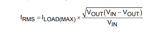
where ILOAD(MAX) is the maximum load current. IRMS has a maximum value when the input voltage equals twice the output voltage (VIN = 2 x VOUT), so IRMS = ILOAD(MAX)/2. Choose an input capacitor that exhibits less than +10°C temperature rise at the RMS input current for optimal long-term reliability.
Step 4: Selecting Output Capacitors
X7R ceramic output capacitors are preferable because of their stability over temperature in industrial applications. The output capacitors are usually sized to support a step load of 50% of the maximum output current in the application, so the output voltage deviation is contained to 3% of the output voltage change. The minimum required output capacitance can be calculated as follows:
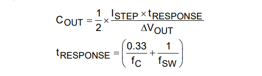
where ISTEP is the load current step, tRESPONSE is the response time of the controller, ΔVOUT is the allowable output voltage deviation, fC is the target closed-loop crossover frequency, and fSW is the switching frequency. For the MAX17504, if the switching frequency is less than or equal to 500kHz, select fC to be 1/9th of fSW. If the switching frequency is more than 500kHz, select fC to be 55kHz. Derating of ceramic capacitors with DC voltage and temperature must be considered while selecting the output capacitor. Derating curves are available from all major ceramic capacitor vendors. In our application, we want to get 150mV output ripple at 1.5A load step. We got COUT = 39.7µF. Considering the derating of ceramic capacitors, we chose 22 x 2µF as the output capacitor.
Step 5: Compensation
The MAX17504 is internally loop compensated. However, if the switching frequency is less than 500kHz, connect a 0402 capacitor, C6, between the CF pin and the FB pin. Use Table 2 to select the C6 value.
| >Switching Frequency Range (Khz) | >C6 (pF) |
| 200 to 300 | 2.2 |
| 300 to 400 | 1.2 |
| 400 to 500 | 0.75 |
Step 6: Setting the Soft-Start Time
The MAX17504 implements adjustable soft-start operation to reduce inrush current. A capacitor connected from the SS pin to SGND programs the soft-start time. The selected output capacitance (CSEL) and the output voltage (VOUT) determine the minimum required soft-start capacitor as follows:
CSS ≥ 28 x 10-6 x CSEL x VOUT
The soft-start time (tSS) is related to the capacitor connected at SS (CSS) by the following equation:

For example, to program a 2ms soft-start time, a 12nF capacitor should be connected from the SS pin to SGND.
Step 7: PCB Layout Guidelines
- All connections carrying pulsed currents must be very short and as wide as possible. The inductance of these connections must be kept to an absolute minimum due to the high di/dt of the currents. Because inductance of a current carrying loop is proportional to the area enclosed by the loop, if the loop area is made very small, inductance is reduced. Additionally, small current loop areas reduce radiated electromagnetic interference (EMI).
- A ceramic input filter capacitor should be placed close to the IC’s VIN pins. Also, its ground loop to PGND should be short. This eliminates as much trace inductance effects as possible and gives the IC a cleaner voltage supply. A bypass capacitor for the VCC pin also should be placed close to the pin to reduce effects of trace impedance. Its ground loop to PGND should be short.
- When routing circuitry around the IC, the analog small-signal ground and the power ground for switching currents must be kept separate. They should be connected where switching activity is minimal, typically the return terminal of the VCC bypass capacitor. Doing so helps keep the analog ground quiet. The ground plane should be kept continuous/unbroken as far as possible. No trace carrying high switching current should be placed directly over any ground plane discontinuity.
- PCB layout also affects the thermal performance of the design. A number of thermal vias that connect to a large ground plane should be provided under the IC’s exposed pad for efficient heat dissipation. The PCB size, copper thickness, and board layer numbers affect the temperature dissipation capacity of the board. For this reference design, it can support a 3A load current with 1oz copper, two layers, and 30.5mm × 40.5mm board. For larger load current, up to 3.5A, you can modify the board by enlarging the board size to 42mm × 38mm.
文件和资源
-
MAXREFDES1048 Design Files2021/2/16ZIP2 M
支持与培训
搜索我们的知识库,获取技术问题答案。我们专门的应用工程师团队也会随时为您解答技术问题。