Using the DS2770 as a 3-Cell NiMH Charger
Abstract
The DS2770 battery monitor and charge controller can be configured to charge either a 1-cell Li-Ion battery pack or a 3-cell NiMH battery pack. This application note presents to the reader a recommended circuit diagram and other considerations for using the DS2770 to charge a 3-cell NiMH battery pack. These other considerations include device configuration and setup, charge source requirements, and component placement in the battery pack. Additionally, typical temperature, voltage, and current curves for a typical NiMH charge controlled by a DS2770 are presented.
Introduction
In order to achieve maximum efficiency when charging a battery, it is necessary to implement charging techniques geared specifically for a battery cell chemistry. For example, negative ΔV or dT/dt termination criteria is used for NiMH cells, while a CC/CV or pulsed-charged technique is appropriate for rechargeable lithium cells.
The DS2770 battery monitor and charge controller can be configured to charge either NiMH or Li+ cells. This application note addresses several key things to consider when using the DS2770 to charge a NiMH battery pack.
NiMH Charging Basics
A NiMH cell has a nominal voltage of 1.2V. Therefore, stacking three NiMH cells together results in a battery pack with a nominal voltage of 3.6V and a maximum voltage of 4.5V.
Typically, a NiMH cell is charged with a constant current until a terminating condition is encountered. The most common way to determine when a NiMH cell has become fully charged is to either observe a drop in the voltage or a rise in the temperature. As the cell becomes fully charged, the voltage drops slightly. At the same time, the temperature rises rapidly as less of the charge source energy goes into actually charging the cell and more of the energy turns into heat.
The DS2770 monitors the temperature of the NiMH battery pack when charging and checks for a change in temperature over a certain time period (dT/dt) to determine when to terminate the charge.
Hardware Setup
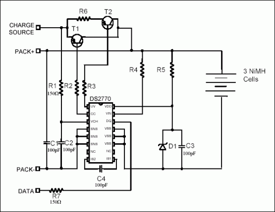
Figure 1 contains the recommended schematic for charging a 3-cell NiMH battery pack. Refer to Application Note 201 for the values of all the components shown in the schematic. In addition to following this schematic, there are some other things to consider when completing the application design.

Figure 1. Recommended schematic for a 3-cell NiMH battery pack.
The charge source for the application should be a constant current or current limited supply with an open-circuit voltage between 5V and 12V. The current supplied by the charge source must be large enough to sufficiently heat the battery pack when a full charge is reached, otherwise, the cells heat too slowly to trip the dT/dt primary charge termination limit. Consequently, charge termination is always reliant on a secondary criteria such as exceeding a maximum temperature or a maximum charge time.
In order to assure charging will terminate as a result of dT/dt primary termination limit, the DS2770 should be placed close to the battery cells with good thermal contact. It may be necessary to include thermally conductive putty between the cells and the DS2770 to enable efficient heat transfer. Additionally, enclosing the cells and the DS2770 in a casing allows the heat generated by the cells as they charge to be transferred to the DS2770 before it is lost to the ambient conditions.
Device Setup
Prior to starting a charge sequence, the DS2770 must be configured for NiMH charge control. The chemistry type to be charged is selectable through the Charge Type (CTYPE) bit (bit 0) of the Status Register. Setting the CTYPE bit to a value of 1 selects NiMH charge control.
The Status Register also contains the Charge Initiation (CINI) bit (bit 1), which determines how a charge is started. A value of 0 in the CINI bit indicates that a charge is only started when a Start Charge command is sent to the device. If the value of the CINI bit is 1, then a charge is started by issuing the Start Charge command or by simply attaching the charge source.
Also, it is necessary to set the maximum charge time in the Charge Time Register (CTR) initialization (memory location 0x34h). When a charge is started, the CTR is initialized to the value that is stored in memory location 0x34h. If the CTR is initialized to a value of 0x00h, a charge begins; however, it terminates in less than 56s. Each bit in the CTR register adds another 56s to the maximum charge time. For example, if a maximum charge time of 3hr is required, then 0xC0h should be written to initialize the CTR. It is necessary to ensure the CTR is initialized to the maximum amount of time that a charge may require. Any value smaller than that could cause the charge to be terminated prematurely.
Starting a Charge
When a start charge condition is encountered, a charge begins unless the DS2770 is outside of the valid temperature range, 0°C to +40°C. Once a charge is started, the DS2770 can go outside the valid temperature range without terminating the charge.
If the battery voltage is ever below 3.0V and a charger is connected, a trickle charge is initiated until the battery voltage is recovered to 3.0V. A Start Charge command is not required to start a trickle charge and it will begin regardless of the setting of the CINI bit.
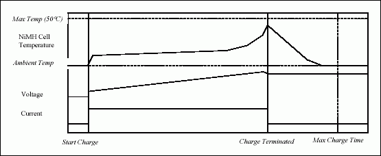
A typical charge profile of a NiMH battery pack using the DS2770 as a charge controller is shown in Figure 2. When the constant current charge begins, the voltage rises due to the loading of the charge source and the temperature rises due to the I²R heating of the pack. The DS2770 ignores the temperature rate termination for the first 5min to avoid false dT/dt detection and uses the most recent temperature measurement to select the appropriate dT/dt threshold.

Figure 2. Temperature, voltage, and current during a typical NiMH charge.
Ending a Charge
The DS2770 provides several ways to terminate a charge. The primary charge termination is by surpassing the dT/dt threshold. The constant current continues until the rate of temperature rise is at or above the selected dT/dt threshold for 2.8min. The effective dT/dt threshold to determine a full charge is 1°C/min regardless of the starting temperature and this occurs at approximately the same time as the voltage drop (or negative ΔV).
Two secondary charge terminations are provided by the DS2770 and are shown and in Figure 2. First is the maximum temperature threshold, which is fixed at +50°C. Second is the maximum charge time, which is programmable and is described in the DEVICE SETUP section of this application note. If the temperature rises above the maximum temperature threshold or the charge time exceeds the maximum limit, charging immediately terminates. These secondary charge termination criteria are included to prevent permanent damage to the battery pack due to over charging. However, it is important to terminate on the primary termination in order to prevent the shortening of the life of the battery pack.
When any of these terminations occur the Charge Status (CSTAT0 and CSTAT1) bits (bits 6 and 7) of the Status Register will both be set to 1 to indicate a "Charge Sequence completed" status.
Conclusion
The DS2770 is easily configured to provide safe and reliable charging of a 3-cell NiMH battery pack. It is crucial to remember two key considerations for proper implementation of this solution. The first is to ensure that there is sufficient heat transfer between the cells and the DS2770 to get an accurate temperature reading of the cells. The second is to ensure the charge source is providing enough current to heat the cells a rate that will exceed the dT/dt termination limit. Once these issues are addressed, and the circuit is implemented, the DS2770 can be configured for NiMH charging through simple settings of on-chip registers and setting the CTR so that it does not expire before the charge has terminated.