Using a Linear Regulator to Produce a Constant Current Source
Abstract
This application note shows how to use linear voltage regulators to provide a constant current. Two circuits are presented, one for high-side and another for low-side current sources. The MAX1818 and MAX1735 LDOs are featured in the designs.
This design idea appeared in the May 11, 2006 issue of EDN magazine.
Linear voltage regulators provide one of the simplest ways to produce a constant current. Because the voltage between a linear regulator's output and ground is tightly regulated, a fixed resistor connected between those two nodes produces a constant current between the output and ground. This configuration applies to both high-side and low-side current sources.
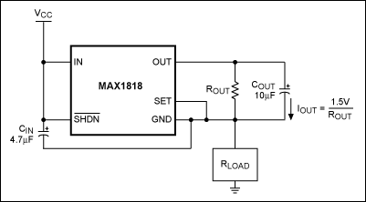
The high-side current source of Figure 1 feeds RLOAD with a constant current, I = 1.5V/ROUT. The positive linear regulator (the MAX1818, available in a 6-pin SOT23 package) provides a fixed output of 1.5V. The voltage between VCC and GND can be as high as 5.5V.

Figure 1. This high-side constant-current source features the MAX1818 LDO and draws 1.5V/ROUT from RLOAD. The circuit requires the voltage for ROUT between the IN and GND terminals to be minimally 2.5V.
There is an important requirement for this circuit: the minimum voltage required for proper operation (2.5V) must be provided between the IN and GND terminals. To satisfy that condition, choose an ROUT value that allows 2.5V to 5.5V between IN and GND. When driving a load of 100Ω maximum with VCC at 5V, for example, the device functions properly with ROUT above 60Ω. That value allows a maximum programmable current of 1.5V/60Ω = 25mA. Voltage across the device then equals the minimum allowed: 5V - (25mA × 100Ω) = 2.5V. This IC can source up to 500mA.
For a low-side current source, consider the circuit of Figure 2. In this design a constant current of I = 2.5V/ROUT is drawn from RLOAD. The IC (the MAX1735, available in a 5-pin SOT23 package) is a negative linear regulator with fixed output voltage of -2.5V. The voltage between GND and IN can be as high as 6.5V.

Figure 2. This low-side constant-current source features the MAX1735 and draws 2.5V/ROUT from RLOAD. This circuit also requires that the voltage for ROUT between the IN and GND terminals is minimally 2.5V.
As in Figure 1, this circuit requires a minimum voltage of 2.5V between the GND and IN terminals. To satisfy that condition, choose an ROUT value that allows 2.5V to 6.5V between GND and IN. When sourcing current from a load of 100Ω maximum with VCC at 5V, for example, ROUT should be greater than 100Ω. That value provides a maximum programmable current of 2.5V/100Ω = 25mA. Voltage across the device is at the minimum: 5V - (25mA × 100Ω) = 2.5V. This IC can source up to 200mA.
Note that both configurations allow the regulator's quiescent current to flow through the load in addition to the programmed IOUT. Quiescent currents are thus a source of error, and one that changes with the voltage applied between IN and GND. This error can be mitigated in either of two ways: choose a voltage regulator with low quiescent current; or choose a voltage regulator whose quiescent current is flat through the operating range, thus allowing you to compensate the error by adjusting the value of ROUT. (Quiescent current for the devices shown in these designs is 130µA typical, and varies less than 40µA from 2.5V to 5.0V.)