Turnkey Power-Supply Solutions Power Pentium® Pro µPs
Abstract
Today's microprocessors (µPs) demand supply rails of lower voltage and greater accuracy than did those of earlier generations. Modern µPs, moreover, feature a start/stop clock operation that demands a fast response to load transients. All these µP requirements can be met with highly integrated power-supply ICs that offer miniature-component circuitry on a small PC board.
As a result of these developments, the earlier and relatively simple 5V/12V power supply has been transformed into a power-supply system that generates multiple low-voltage outputs with high accuracy and high efficiency. Such systems must also respond quickly to changes in load current. The Pentium® Pro µP, for example, can produce 0.5A to 10A load-current steps that require the power supply to respond within 350ns, at 30A/µs.
Desktop and notebook computers require several different low-level supply voltages to operate their internal memory, logic, and disk-drive circuitry. These computers employ a combination of 5V, 3.3V, and 2.XV in most cases. Two key requirements for this task are high-efficiency dc-dc converters and synchronous rectifiers.
The synchronous rectifier in a switch-mode power supply consists of a low-resistance conduction path across the Schottky diode, for the purpose of improving power-conversion efficiency. MOSFETs usually provide this low-resistance path, but bipolar transistors and other semiconductor switches are also suitable. The forward-voltage drop across a switch-mode rectifier degrades efficiency in proportion to the VIN/VOUT ratio. As standard supply voltages have been revised downward repeatedly, the drop has become an increasing fraction of VOUT, producing an efficiency loss that calls for closer attention to rectifier design.
The following discussion develops a complete power-supply design that meets the Pentium Pro specifications for accuracy and fast transient response. It occupies only 3.1" × 1.5" of board area. A second, higher current board offers output currents to 15A and an option for moderate- or high-accuracy output voltage. Also presented is the design of a 1.5V power supply used to terminate the Gunning Transceiver Logic (GTL) bus and other high-speed buses associated with processors such as the Pentium Pro.
To meet Intel's Pentium Pro power requirement, Maxim designed a plug-in power-supply module with a standard connector that plugs into a mating socket on the motherboard. This dc-dc converter module is based on the MAX797 BiCMOS controller U1 (See photo, top of Figure 1, and Figure 2). Configured in the fixed-frequency PWM mode, U1 operates with a synchronous rectifier (N2) that improves efficiency at low output voltages.
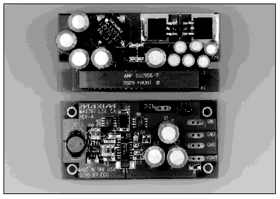
Figure 1. A power-supply module for Pentium Pro microprocessor systems (top) and a bus-termination supply for Gunning Transceiver Logic (bottom) both depend on the MAX797 step-down PWM controller.
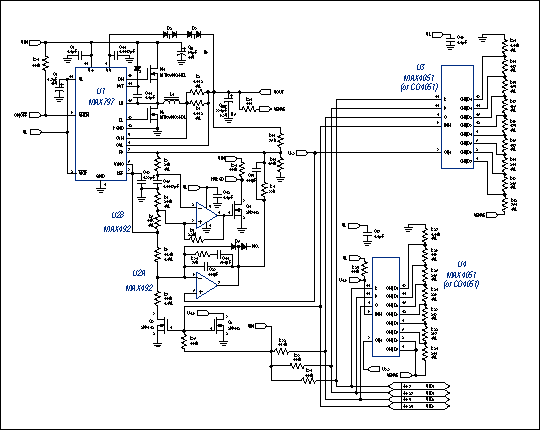
Figure 2. This power-supply circuit generates 2.1V to 3.5V at 11.2A, for Pentium Pro microprocessor systems.
This module accepts, via the J1 connector pins, an input voltage of 4.5V to 6V and a 4-bit configuration code from the Pentium Pro (pins Vid0-Vid3). The code adjusts the module's output voltage to that required by the µP at its supply pins. Each bit is either 5V (logic 1) or ground (logic 0). The result is 16 available codes that set the output voltage in 100mV increments from 2.1V to 3.5V.
To minimize cost, the single D/A converter usually employed for output-voltage adjustment has been replaced with a strip of resistor divider and two MAX4051 (or CD4051) 8-1 multiplexers. U1's fixed 2.5V reference enables the circuit to regulate output levels below 2.5V. R6 and R7 divide down this voltage and feed it to an integrator formed by U2A, C14, C23, and R36. Reduced from 2.5V to 2.1V, this voltage is summed with a directly coupled feedback signal (to ensure rapid response to transients), and fed to the main high-speed comparator at U1's FB terminal. The other half of U2, op amp U2B, generates an open-drain power-good signal (PWRGD) that goes low whenever the output voltage is out of tolerance.
During power-up, diode D5 (between U2A pins 6 and 7) limits the output overshoot, and capacitor C10 (U1, pin 1) reduces the input surge currents. An internal soft-start circuit holds C10 discharged to ground during shutdown (OUTEN = 0V). When OUTEN goes high, C10 is charged by an internal 4µA current source, and the main output capacitor, COUT, charges up slowly, depending on its value. The maximum current limit is reached within 5ms.
D2 and D3 protect the converter during a continuous short circuit. The input capacitor (CIN) assists in decoupling load transients from the main input and in meeting the input-ripple requirement, which is approximately half the output current. COUT provides bulk capacitance and low ESR. For load steps of 0.2A to 11.2A (the module's maximum output current), the output transient is typically ±50mV and the output ripple is typically 15mV.
The controller IC in Figure 2 (MAX797) is also suitable for higher power 5V step-down applications in which efficiency, board space, and output-voltage accuracy are critical. One such circuit is the synchronous buck dc-dc converter of Figure 3. Designed to operate with a minimum number of small external components, it features a 300kHz switching frequency, 15A (or 20A) maximum output current, and a 2V to 3.5V output range. The low-cost, high-slew-rate, n-channel switching MOSFETs (N1 and N2) provide efficiencies (without a heat sink) that exceed 90% at high IOUT.
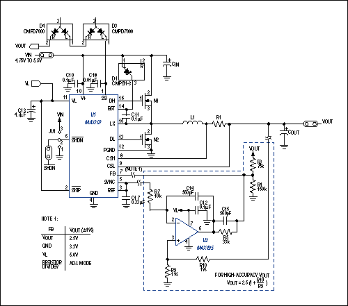
Figure 3. This high-IOUT circuit can deliver maximum output currents of 15A or 20A (see text).
| Component | Load Current | |
| 15 Amperes | 20 Amperes | |
| Input Voltage | 4.75V to 5.5V | 4.75V to 5.5V |
| N1 MOSFET (High Side) | MTB75NO3HDL (MOT) | MTB75NO3HDL (MOT) |
| N2 MOSFET (Low Side) | MTB75NO3HDL (MOT) | MTB75NO3HDL (MOT) |
| Input Capacitor (CIN) | 3 × 330µF (Sanyo 6SA330M or 10SA330M) | 4 × 330µF (Sanyo 6SA330M or 10SA330M) |
| Output Capacitor (COUT) | 6 × 330µF (Sanyo 6SA330M) | 8 × 330µF (Sanyo 6SA330M) |
| Sense Resistor (R1) | 2 in parallel (Dale WSL-2512-R009) | 3 in parallel (Dale WSL-2512-R009) |
| Power Inductor (L1) | 1.5µH, 20A (Coilcraft D05022P-152HC) | 1µH, 25A (Coilcraft DO5022P-102HC) |
The IC provides fixed-output connections for applications that tolerate ±4% output-voltage accuracy. Connecting the FB terminal (pin 7) as listed in the figure provides outputs of 2.5V, 3.3V, or 5.0V. For higher accuracy, you can add an op amp with rail-to-rail output capability (U2) that controls FB by comparing a scaled version of VOUT with the controller's reference voltage. Resistors R9 and R10 then set the output level: VOUT = 2.5 (1 + R10 / R9). Either feedback arrangement enables the board to supply VCC for multiple microprocessors.
U1 provides excellent line and load regulation, with a micropower shutdown that lowers the quiescent current to a maximum of 3µA. It also includes soft-start circuitry that limits the input surge current at start-up by gradually increasing the internal current limit. Soft-start causes the output capacitors to charge relatively slowly. In this case, the 0.01µF soft-start capacitor (C18) allows the output current to reach its maximum limit within 10ms. Table 1 lists component choices that enable the Figure 3 circuit to generate 2.5V at 15A or 20A.
The new microprocessors not only demand lower voltage rails; they also require high-speed, low-voltage buses for the next generation of computers. These buses—GTL, Futurebus, and Rambus, for example—require low-voltage terminations that reduce the signal-voltage swings. Other buses, such as center-terminated transceiver logic (CTT) and high-speed transceiver logic (HSTL), have center terminations that require the terminating power supply to both sink and source current.
Thus, a bus-termination power supply must generate 1.5V for a GTL bus or 0.75V for a CTT or HSTL bus, and be able to sink and source current into the termination resistors. Providing 1.5V at 5A, the Figure 4 circuit meets these requirements with a MAX797 controller that operates with synchronous rectification for high efficiency (Figure 5). The circuit's sink capability at low voltage is provided by the combination of synchronous switch N2 and a circuit topology that allows the inductor current to reverse. (See bottom of the Figure 1 photo.)
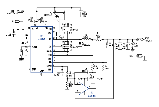
Figure 4. An accurate 1.5V step-down converter powers the termination resistors in a GTL data bus.
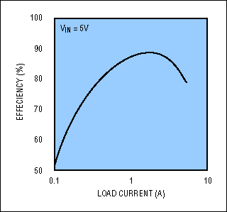
Figure 5. The low-VOUT (1.5V) GTL-bus power supply of Figure 5 offers maximum efficiency for load currents between 1A and 2A.
Pulling the active-low SKIP logic input high enables continuous-conduction mode for the inductor current, and also allows this current to flow from the output back through the inductor and N2 switch to ground. You can easily change the output voltage from 1.5V to 0.75V by changing R5 from 66.5kΩ to 232kΩ. As in the Pentium Pro power supply, this circuit achieves regulated outputs below 2.5V by dividing down the internal 2.5V reference (pin 3), integrating the result, and combining it with a directly coupled feedback signal.
The output sink current does not flow directly to ground as it would in a comparable linear design. Instead, the synchronous buck topology of this circuit works in reverse, becoming a boost topology that enables the sink current to constitute a net positive flow back into the 5V input supply.