Reverse Battery Charger Protection
Abstract
Combining a linear-mode single-cell lithium-ion battery charger (MAX1551) with a comparator (MAX9001) and n-channel FET adds a layer of reverse-battery protection that protects a single cell lithium-ion battery charger and battery from damage due to backwards insertion.
A similar version of this article appeared in the March 1, 2007 issue of PET magazine.
Many battery powered applications use diodes for reverse battery protection. However a diode does not always protect a battery charger when the battery is inserted incorrectly. Sometimes when the battery is inserted backwards it can cause a large amount of current flow through the charging circuitry, possibly destroying both the battery and charger. Many battery-charger designs rely on mechanical means that only allow a battery or power plug to be inserted one way. Cell phone batteries are mechanically shaped so that they can be inserted with the proper orientation. Even the charger cord is mechanically shaped to allow insertion in one way.
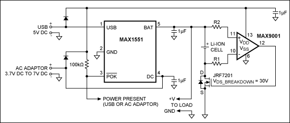
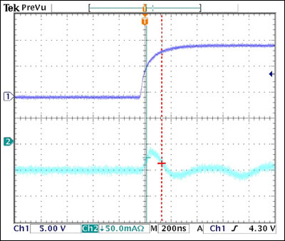
The simple circuit in Figure 1 adds another layer of reverse battery protection and protects a single cell lithium-ion battery charger and battery from damage due to backwards insertion. In the circuit, the MAX1551 linear mode single-cell lithium-ion battery charger delivers the charging current to the cell from either an AC adaptor or USB power supply. During normal operation the MAX9001 output is high and the FET is on. When the battery is inserted backwards, the MAX9001 output goes low and the FET turns off, thus blocking current flow. The rapid switching of the FET keeps the current surge to less than 50mA and that surge lasts for less than 200ns before dampening as shown in the lower scope trace (Figure 2).

Figure 1. Schematic for simple reverse battery charger protector.

Figure 2. The top curve simulates the insertion of the battery and the bottom curve is the current measured through a Tektronix® current probe.
When the cell is inserted backwards, the potential at the inverting terminal of the MAX9001 increases beyond the supply voltage. Resistor R1 limits the amount of overvoltage current sourced through the on-chip electrostatic discharge (ESD) diode. Larger resistor values can be selected to limit the reverse battery leakage current through the ESD diodes, but the tradeoff is slower operation and larger transients. In the test circuit used, VCC = +5V and R1 = R2 = 50kΩ. The low-side FET enables this type of circuit to work for multi-cell batteries as long as the comparator inputs are within the absolute ratings of the comparator. Connecting battery in reverse without the external protection will destroy the MAX1551 due to the high current surge.