Radio Susceptibility - Cure with Antibiotic, Vaccine, or the Laws of Physics?
Abstract
Engineers often wish that radio susceptibility (RS) or radio immunity could be cured with an antibiotic, a vaccine, or some form of cure-all. Unfortunately, solving the RS problem is not that easy. Indeed, the laws of physics apply. In this article we discuss sources of RS. We also offer tips and hints to protect systems, power supplies, printed circuit boards (PCBs), and electronic components from radio frequency interference.
A similar version of this article appeared on November 12, 2011 in the digital version of EE Times magazine.
Introduction
Blue-green bread mold has been used for hundreds of years to treat infections. Then in 1932, Alexander Fleming recognized the antibiotic effect and named the drug penicillin. He was not the first to discover the therapeutic value, but he started a chain of events that led to the commercialization and mass production of penicillin in the 1940s. Literally millions of lives have been saved by "purified bread mold".1
How often has man wanted to take a medicine and apply it as a cure for another problem? More often than we probably realize. While penicillin has been a panacea for humans, it does not work for radio susceptibility (RS). For this problem, we must turn to the laws of physics, which do teach us how to control susceptibility to radio interference.
Understanding the Nature of the RS Problem
According to Sayre,2 susceptibility is "how easily an electronic device is adversely affected by another device's electromagnetic field." In common terms, an electromagnetic field is a radio signal. Electromagnetic interference (EMI) and radio frequency interference (RFI) are related and many times used interchangeably.
"Digital ICs are immune from RFI, so why aren't analog ICs?" asks a new digital engineer. Digital ICs are affected by RFI, but not so obviously. In fact, digital is analog with thresholds.3 Once the digital signal level is higher or lower than the two thresholds, low-level RFI can be ignored in most cases. However, that is not always true, because edge jitter is caused by interference on the transitions. Most digital devices are protected at the system level. So, it is not economical to double or triple the cost of a digital logic gate to add RFI protection, especially when most customers do not need it.
RS is a system specification primarily for radio Integrated circuits (ICs), with a few exceptions. Most of these circuits in most systems are isolated from the external world by the case (shielding) power-supply decoupling networks, power line filters, and isolation circuits. There are two exceptions to this norm: radio devices that are directly connected to antennas, and other devices connected to system input and output ports. Ed Hare4 discusses interference issues with consumer devices, cable TV, TV sets, VCRs, telephone, and other audio systems from the amateur radio enthusiast's (HAM) prospective. Chapter 17 of his book simplifies the U.S. RFI regulations and standards, and Appendix C reprints the FCC's Interference to Home Entertainment Equipment Handbook.
The
Adding expense and complexity to get RS protection for internal system parts is not cost effective. This, then, leads to another question. Why are analog ICs protected from electrostatic discharge (ESD)?
Protecting Analog Connections with the Outside World
ESD requires two different protections levels: ESD inside the IC protects it during handling and assembly; system-level ESD is at the input/output (IO) ports, is more robust, and requires discrete devices that will not fit inside the IC.
The system connections with the outside world are where RS matters most. Typical examples are where AC power enters the system box or where signals enter a device like the TV antenna, satellite dish, or Ethernet cable. The next concern is the exit points for cables like audio and video and network connections.
Power Supply Connections (Conducted Emissions)
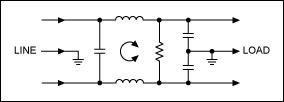
At the AC-powerline entry point is a lowpass filter block. This protects the system against any RFI that enters from external sources. Since the filter is reciprocal, it also prevents signals from the system and the switching power supplies from propagating out onto the AC powerline. This filter is passive, made of common-mode chokes (inductors) and capacitors. A schematic for a typical Corcom® power filter is shown in Figure 1.

Figure 1. Common-mode choke powerline filter.
Input and Output RFI Protection (Conducted Emissions)
Corcom also makes other filter modules for DC voltage, RJ-11 jacks (telephone), and RJ-45 jacks (Ethernet). These modules prevent RFI from intruding into the system enclosure, and attenuate any spurious signals generated in the system from leaving the enclosure. The entrance and exit points are typically protected with lowpass filters made from passive components. An exception is made for radio and TV radio frequency signals which are protected by bandpass filters. In effect, signals both lower and higher than the wanted radio frequencies are blocked.
EMI and Radiated Emissions (RFI)
Radiated signals come and go through the side of a system container. Plastic boxes are common because they are inexpensive, can be made in compelling shapes, and protect from electric shock hazards. However, EMI and RFI propagate directly through the plastic. As a result, additional shielding must be provided with metal shields6 or conductive coatings inside the box. Conductive coatings and light sheet metal provide electrostatic protection, while magnet shields require heavier magnetic materials.7 In this context printed circuit board (PCB) design and grounding are critical,8 as are DC power and decoupling.9
RS in Semiconductors and ICs
The simplest semiconductor is a diode, a small one-way switch. Figure 2 shows a crystal radio, a design quite common from the 1930s.10 At the top is an antenna and at the bottom is a ground; there is no tuning provided to elect between stations. In those days, there just were not many stations around and the nearest and loudest overpowered the others. The diode rectified the RF, converting it into audio energy that the high-impedance earphone made into sound.

Figure 2. Crystal radio schematic.
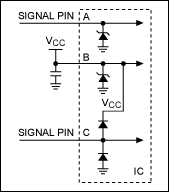
Was the diode susceptible to the radio signal? Yes indeed and that is the whole point of including it here. Figure 3 is the most common circuit found inside modern ICs. This circuit manages the ESD by using diodes in the ESD structure. As in the case of the crystal radio, the ESD diodes can also demodulate a radio signal. Thus it is necessary to take steps to protect ESD diodes from radio signals.

Figure 3. This schematic for a modern radio circuit with ESD protection.
What will happen if an RF signal is applied to a signal pin or the VCC power pin? The circuit's function reverts into a crystal radio. Now the obvious question is: are common IC ESD diodes susceptible to a radio signal? Absolutely. As seen in Figure 3, the VCC line has a capacitor connected to ground. This provides a path through the capacitor for radio signals to be shunted to ground. For example, the U.S. AM broadcast radio stations are in a band around 1MHz. If the capacitor in Figure 3 (B) is 0.1µF, it will reduce the AM radio signal because the capacitor is low impedance at that frequency.11
In fact, any nonlinearity in a circuit will rectify spurious signals. Amplifiers with excellent linearity will rectify less than those with poor linearity. Overloading even a superior amplifier will cause significant distortion and nonlinearity.
What about 3-terminal voltage regulators such as LDOs (low dropout) and voltage references? They comprise an internal voltage reference (typically a bandgap or zener diode), an amplifier, and a pass transistor. The amplifier uses feedback to compare the reference voltage with the output voltage, and provide an error signal that corrects the output. The wanted output is a stable DC voltage. The regulator needs to operate when the input line voltage changes and if the output load changes, so some correction speed or bandwidth is needed. However, the correction speed must be limited to ensure smooth control and stability. Consequently, the typical bandwidth is 200kHz to 1MHz, maximum. Now one asks, what happens when a high-frequency radio signal around 800MHz is applied to any terminal (the input, output, or ground)? The radio signal will not be attenuated or corrected by the feedback loop. Thus the radio signal propagates through the regulator. Thankfully the regulator requires power supply decoupling to remove such radio signals. The capacitors only work below their self-resonance points.6, 12 That is why one might see four decoupling capacitors on a device that has to reject RFI.13
Additional information on grounding, power-supply decoupling, and board layout is contained in the references 11 through 15.
Summary
Most common ICs are not tested for radio susceptibility. This is because in 99.9% of the applications the system is already protected from RFI and EMI, both from intrusion into the system and radiation out of the system. Radio ICs are an exception. Since they need RF to function, these circuits must combine internal and external bandpass filtering so only the wanted frequencies are allowed into and out of the system.
参考电路
- Alexander Fleming in Time Magazine, www.time.com/time/magazine/article/0,9171,990612,00.html.
- Sayre, Cotter, Complete Wireless Design, McGraw-Hill, IBSN 978-0-07-154452-8, page 653.
- Analog application note 4345, "Well Grounded, Digital Is Analog."
- Hare, Ed, editor, The ARRL RFI Book, American Radio Relay League, ISBN 0-87259-683-4.
- See the American Radio Relay League site at www.arrl.org/files/file/Technology/FCC%20RFI%20Information/tvibook.pdf.
- Burgoon, John R., Jr., Fundamentals of Electrical Shield Design, Insulation/Circuits, August 1970, (Lake Publishing).
- Ott, Henry W., Electromagnetic Compatibility Engineering, ISBN 978-0-470-18930-6, chapter 7 on shielding.
- Sayer, op cit., chapter 13, "EMI Control and Printed Circuit Board Layout;" Hare, op cit., chapter 16, "RF and Transient Immunity;" Joffe, Elya B., and Lock, Kai-Sang, Grounds for Grounding, ISBN978-0471-66008-8, chapter 9, "Grounding on Printed Circuit Boards."
- Ott, op cit., chapter 11, "Digital Circuit Power Distribution."
- Various accounts of the history of early radio are available. See https://www.californiahistoricalradio.com/radio-history/100years/; https://bayarearadio.org/#KQW; www.charlesherrold.org/.
- Analog application note 4992, "Reduce the Chances of Human Error: Part 1, Power and Ground." Electronic system errors are typically analog, not digital.
- Analog application note 4993, "Reduce the Chances of Human Error: Part 2, Super Amps and Filters for Analog Interface." Interface is an expert subject that requires training. This application note provides some basic reminders and concepts about amplifiers and filters.
- Ott, op cit., chapter 11.4 for a discussion of capacitor sizing.
- Analog application note 4605, "Avoid Design Misinterpretations that Put System Operation in Jeopardy." Three case studies illustrate how some simple analysis and a proper understanding of the laws of physics can help designers.
- Analog application note 4991, "Oops...Practical ESD Protection vs. Foolhardy Placebos." Suggests practical ways to protect electronic systems.