Multiple-Pulse Generator Aids IC Testing
Abstract
Comprising a quad op amp, logic gate, pushbutton switch, debounce circuit, and D flip-flop, this circuit substitutes for a microcontroller or arbitrary-waveform generator in producing the serial digital codes needed to program a single IC input.
This design idea appeared in the September 1, 2009 issue of Test & Measurement World magazine.
Because ICs continue to shrink in size, even as their complexity increases, the IC packages have grown smaller even as their pin count drops or remains constant. The resulting burden on pin functionality has created a need for pin-saving measures like serial programming. For example, multiple pins might have been available in the past for programming an IC's current or voltage limit, but today's IC may have to encode that limit as a set number of pulses on a serial line.
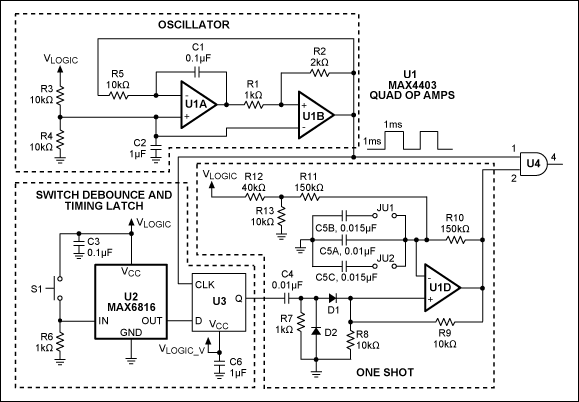
A circuit like that of Figure 1 is therefore useful when a microcontroller or arbitrary-waveform generator is not available. Comprising a quad op amp, logic gate, pushbutton switch, debounce circuit, and D flip-flop, it generates 500Hz bursts of one, two, or three pulses.

Figure 1. This serial-pulse generator is jumper-programmed to produce 1-, 2-, or 3-pulse bursts.
In the oscillator section (taken from Maxim application note 3201, "Pulse-Width Modulator Operates at Various Levels of Frequency and Power") the integrator (U1A) produces a triangle wave at its output, which in turn enables U2B to create an output squarewave with 50% duty cycle.
In the "switch debounce and timing latch" section, pushbutton switch S1 connects to a CMOS switch debouncer (MAX6816), which ensures a noise-free output for driving the D flip flop. The D-input logic level passes to the Q output only on the rising edge of CLK. The one-shot section (described below) is also timed with the rising edge of the CLK signal, to ensure that the output pulses from U4, whether single or multiple, have the same width.
In the one-shot section, a third op amp from the quad device U1 sets the number of pulses to be generated. The flip-flop output pulls the C4 voltage high, driving the positive input of U1D high. The U1D output then goes high, and sets the voltage on its positive input via the R8/R9 divider. The R10–R13 network and C5 then produce an increasing voltage across C5. When the voltage at U1D's negative input exceeds that of its positive input, the U1D output goes low.
The output signals from U1B and U1D connect to an AND gate, whose 500Hz output persists for an interval that allows just the number of pulses required. Figure 2a–c shows the waveforms associated with 1-, 2-, and 3-pulse outputs. Two jumpers (JU1 and JU2) set the number of pulses by altering the value of C5. JU1 and JU2 open allows one pulse at the AND-gate output, closing (shunting) JU1 only allows two pulses, and shunting both jumpers allows three pulses.

Figure 2. The Figure 1 circuit operates with single pulses (a), double pulses (b), or triple pulses (c). The waveforms shown in each graph are the U1B output (top), U1D output (middle), and U4 output (bottom).