Low-Current Charger Provides Battery Backup from USB to 1-Cell Applications
Abstract
The circuit provides a 1-cell Li ion backup battery charger for low-current devices performing resistor-limited current sharing.
A similar version of this article appeared February 2014 on How2Power.
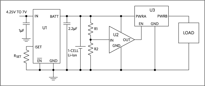
A simple circuit sometimes needs to charge a 1-cell Lithium-ion (Li+) battery from a USB power source and simultaneously provide backup power for low-current-consumption devices. The circuit in Figure 1 shows such a solution.
Today, most handheld devices use USB as the power source. This design circuit includes a linear, 1-cell charger that accepts a DC power source to charge a 1-cell Li+ battery. The power source provides load current while charging the 1-cell battery. The circuit performs resistor-limited current sharing. The maximum current available is fixed by the setting resistor and that current will primarily drive the load. When the load does not require the full maximum current, the remaining current is available to charge the battery. When the DC source is not available and the cell voltage drops to a user-determined level, a voltage monitor activates an ultra-low-resistance switch to disconnect the cell from the load. This operation avoids a deep discharge of the cell.
U1 (the MAX8814), a linear Li+ battery charger, accepts 4.25V to 7V, which covers the USB range. The input of U1 can sustain a source voltage of up to 28V, but the output of U1 is disabled when the DC source exceeds 7V. The charge voltage for U1 is factory fixed to be 4.2V. The maximum charge current is user-adjustable to ICHARGE = 1596V/ RSET. Maximum charge current is 570mA when RSET is 2.8kΩ. U2 (the MAX9646), a low-power comparator with a 0.2V integrated reference connected to the noninverting input, monitors the cell voltage to provide a push-pull output. VTRIP is 0.2V × (R1 + R2)/R2. The trip voltage is 3.5V with R1 = 82.5kΩ and R2 = 5kΩ. The output of U2 turns off U3 (the MAX14680), a 0.01Ω battery switch, to disconnect the cell from the load when the cell voltage drops to 3.5V.
The circuit is space-saving as U1 is 2mm × 2mm, U2 is 1mm x 1mm, and U3 is 1.3mm × 1.7mm, and it requires only five external components.

Figure 1. Low-Current Charger Provides Battery Backup from USB to 1-Cell Applications.