Design Note 241: Fast Op Amps Operate Rail-to-Rail on 2.7V
The new LT1806 and LT1809 are fast operational amplifiers with rail-to-rail inputs and outputs. The LT1806 is optimized for low noise (3.5nV/√Hz) and offset (100μV typical, 550μV max) and has a 325MHz gain bandwidth product. The LT1809 is optimized for low distortion (–90dBc to 5MHz) and has a 180MHz gain bandwidth product. Both amplifiers have 85mA output drive capability and are fully specified over commercial and industrial temperature ranges on 3V, 5V and ±5V supplies.
Parallel Composite Amplifier Achieves Low Distortion into Heavy Loads
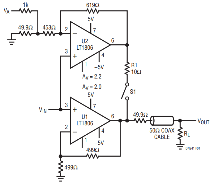
Achieving low distortion is difficult enough and driving heavy loads only makes the undertaking more difficult. Figure 1 shows a parallel composite topology where each amplifier is given a different responsibility. Amplifier U1 is configured in a standard gain of 2 to account for the eventual attenuation caused by the 50Ω output divider. Amplifier U1 alone can drive the load, but its distortion figures would suffer. Therefore, amplifier U2 is added in a slightly higher gain and its output is coupled to the circuit output through the attenuating 10Ω resistor, with the product of the gain and the attenuation set to match U1’s gain of 2. In this way, the heavy load current is supplied by U2’s output and is not seen by U1. Although the heavy load current on U2 will cause it to generate higher distortion, these distortion products are decoupled by the 10Ω resistor and corrected by U1. Basically, U2 supplies the power and U1 supplies the precision.

While this provides improvement, it is still possible to do better. Normally, lower distortion is achieved by putting the output into “Class A” operation, in which the bias current is higher than the peak load current. This is often done with a simple load resistor to one of the supply rails. Unfortunately, in cases where load current is already high, additional load current will only make matters worse. However, a kind of “tracking” Class A operation can be achieved by putting a small offset voltage into the power amplifier, U2. This causes a slight DC shift in its output and increases the bias current of U1’s output stage. The DC offset is injected at VA through R7 and can be dynamically adjusted to suit real-time requirements. Table 1 shows results achieved with a 1VP-P input signal at 2.5MHz with ±5V supplies, with the last entry showing 3VP-P throughput. Note that because the circuit shown is noninverting, its input impedance is high and is easy to drive.
| VIN | S1 | VA | RL | VOUT | Harmonics | ISUPPLY | Note | |
| 2nd | 3rd | |||||||
| 1VP-P |
Open | 0V | 1M | 2VP-P | –92dBc | –98dBc | 22mA | Low distortion at light load |
| 1VP-P |
Open | 0V | 50Ω | 1VP-P | –80dBc |
–84dBc | 24mA | Load increases, distortion worse |
| 1VP-P |
Closed | 0V | 50Ω |
1VP-P | –90dBc |
–99dBc | 25mA | U2 helps, distortion better |
| 1VP-P |
Closed | 1.5V | 50Ω |
1VP-P | –94dBc |
–99dBc | 28mA | Add offset, distortion better yet |
| 3VP-P | Closed | 1.5V | 50Ω | 3VP-P | –85dBc | –77dBc | 36mA | Results at higher amplitude |
Among the benefits of this parallel composite topology over series composite topologies is that it does not require onerous attention to compensation and does not reduce the effective bandwidth of the op amps. The trade-off is that supply current increases, but the designer should remember that a 3VP-P signal requires ±30mA of peak current itself, so a 36mA supply current is modest considering the low distortion levels being achieved. This example was shown using two LT1806’s for low noise and high bandwidth, but depending on the requirements other amplifiers can be configured in this topology as well.
Rail-to-Rail Pulse Width Modulator
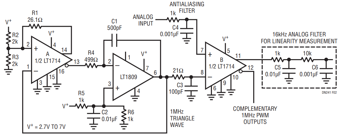
Using the LT1809 Binary modulation schemes are used in order to improve efficiency and reduce physical circuit size. They do this by reducing the power dissipation in the output driver transistors. In a normal Class A or Class AB amplifier, voltage drop and current flow exist simultaneously in the output transistors and power losses proportional to V • I occur. In a binary modulation scheme, the output transistors, whether bipolar or FET, are switched hard-on and hard-off so that voltage drops do not occur simultaneously with current flow. The circuit of Figure 2 shows an example of a binary modulation scheme, in this case pulse width modulation.
The LT1809 is configured as an integrator in order to generate nice linear rail-to-rail voltage ramps. The polarity of the ramp is determined by the output of comparator A into R4. The heavy hysteresis of R1 around comparator A combined with the feedback of the LT1809 force the devices to perpetually reverse each other, resulting in a 1MHz triangle wave. This constitutes the usual first half of any pulse width modulator, but the forte of this particular implementation is that it is rail-to-rail allowing a full-scale analog input. Once the triangle wave is achieved, the remainder of the pulse width modulator is easy, and is constituted by doing a simple comparison using the second half of the LT1714. The triangle wave and the relatively slow moving analog signal (the one to be modulated or to do the modulation, depending on how you look at it) are fed into the inputs of comparator B, whose output is then the PWM representation of the analog input voltage. The higher the analog input voltage, the wider the output pulse. The time averaged output level is thus proportional to the analog input voltage. This binary output can then be fed into power transistors with direct control over motor or speaker winding current, for example, with their inherent lowpass characteristic. Care must be taken to avoid cross conduction in the output power transistors.
The linearity of the pulse width modulated signal can easily be ascertained by putting a simple 2-pole RC filter at the output (as shown in Figure 2). This demodulates the signal which can then be viewed and compared with the original input signal on an oscilloscope. Using a spectrum analyzer and a 1kHz reference signal, this circuit’s distortion products were measured as better than –50dBc (0.3%) to about 3.5VP-P, degrading to –30dBc (3%) as the circuit clips at 5VP-P on a single 5V supply.

