Design Note 451: Current Sense Amp Inputs Work from –0.3V to 44V Independent of Supply
Introduction
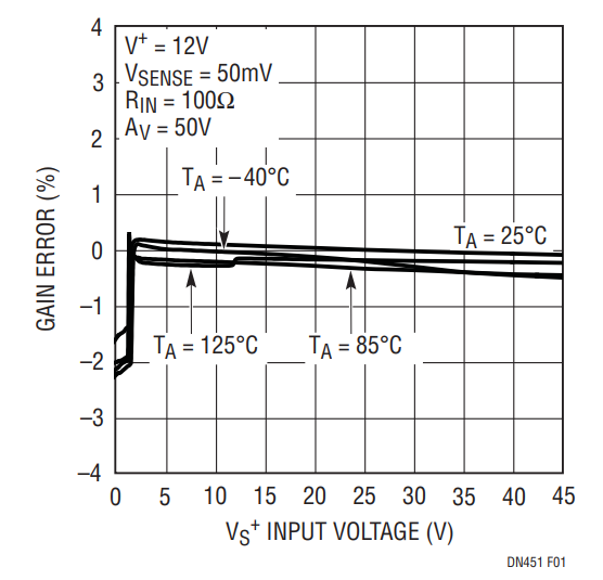
Monitoring current flow in electrical and electromechanical systems is commonly used to provide feedback to improve system operation, accelerate fault detection and diagnosis, and raise efficiency. A current monitoring circuit usually involves placing a sense resistor in series with the monitored conductor and determining the voltage across the sense resistor. To minimize power loss in the sense resistor it is kept as small as possible, resulting in a small differential voltage that must be monitored on top of what may be a fairly large varying common mode voltage. The LT6105 is an ideal current sense amplifier for this application. Just give it any reasonable supply voltage, say 3V, and its inputs can monitor small sense voltages at common modes of –0.3V to 44V and anything in between. The accuracy of the LT6105 over this range is displayed in Figure 1.
Figure 1. Gain Error vs Input Common Mode.
Solenoid Monitoring
The large input common mode range of the LT6105 makes it suitable for monitoring currents in quarter, half and full bridge inductive load driving applications. Figure 2 shows an example of a quarter bridge. The MOSFET pulls down on the bottom of the solenoid to increase solenoid current. It lets go to decrease current, and the solenoid current freewheels through the Schottky diode. Current measurement waveforms are shown in Figure 3. The small glitches occur due to the action of the solenoid plunger, and this provides an opportunity for mechanical system monitoring without an independent sensor or limit switch.
Figure 2. Solenoid is Pulled Low, Freewheels High. Input Travels from 0V to 24.3V.
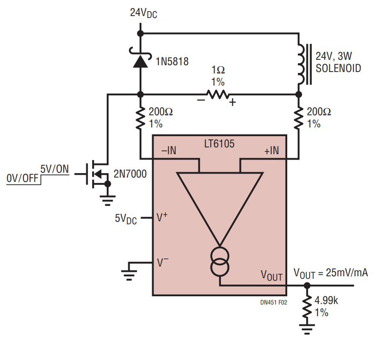
Figure 3. Solenoid Waveforms: MOSFET Gate, Solenoid Bottom and Current Sense Amp Output. Bumps in the Current Result from Plunger Travel.
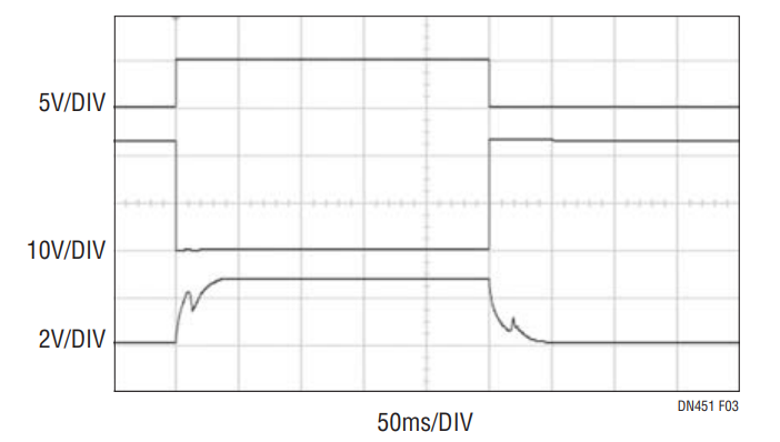
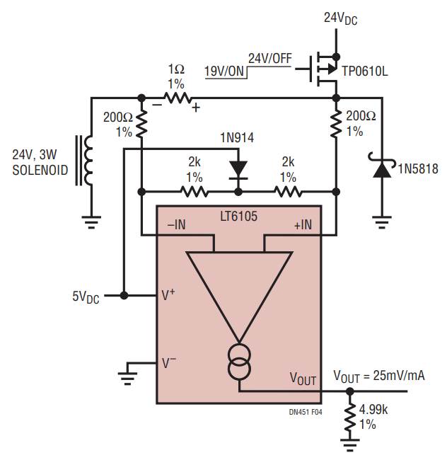
Figure 4 shows another solenoid driver circuit, this time with one end of the solenoid grounded and a P-channel MOSFET pulling up on the other end. In this case, the inductor current freewheels around ground, imposing a negative input common mode voltage of one Schottky diode drop. This voltage may exceed the input range of the LT6105. This does not endanger the device, but it severely degrades its accuracy. In order to avoid violating the input range, pull-up resistors can be used as shown in Figure 4.
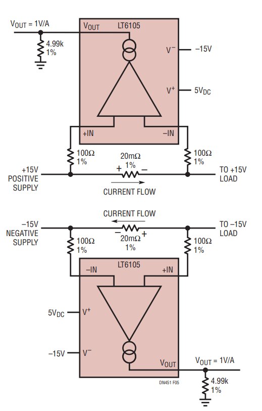
Figure 4. Solenoid is Pulled High to 24V, Freewheels Low to a Schottky Below Ground. LT6105 Inputs are Kept Within Range by 2k Pull Ups. Figure 5. The LT6105 Can Monitor the Current of Either Positive or Negative Supplies, Without a Schematic Change. Just Ensure that the Current Flow is in the Correct Direction.

Supply Monitoring
monitor, and another LT6105 as a simple negative supply monitor. Note that the schematics are practically identical and both have outputs conveniently referred to ground. The only requirement for negative supply monitoring, in addition to the usual constraints of the absolute maximum ratings, is that the negative supply to the LT6105 must be at least as negative as the supply it is monitoring.
Conclusion
Current measurement is popular because it offers improved real time insight into matters of efficiency, operation and fault diagnosis. The wide input range of the LT6105 and its accuracy over that range make it easy to measure currents in a variety of applications.
作者
