How to Collect Data from an Embedded System for Use in MATLAB
Abstract
This application note and supporting source code provide a simple portable framework for accomplishing the real-time transport of data between the embedded system and a PC running MATLAB using a serial transport such as RS-232.
Introduction
Embedded control and measurement systems can often benefit from high-level algorithm development using tools such as MATLAB®. To accomplish this, it is necessary to export data from the embedded system to a PC. While MathWorks offers add-on packages that facilitate embedded algorithm development, these packages can be expensive. Oftentimes, a simple way of collecting data from an embedded system for basic analysis is all that is required.
This application note and supporting source code provides a simple portable framework for accomplishing the real-time transport of data between the embedded system and a PC running MATLAB using a serial transport such as RS-232.
Requirements
The implementation of the architecture described in this application note has been tested on the MAX35103EVKIT2# PCB, which is part of the MAX35103EVKIT2 EV kit software, but it can easily be ported to other platforms. The MAX35103EVKIT2 is recommended for initial evaluation and reference.
This application note assumes that the user has a basic understanding of MATLAB, MATLAB MEX, the C language, and the Win32® API. Experience with IAR Systems®-based technologies, ARM®-based systems, and Visual C++® is also helpful.
The following tools are required for full evaluation:
- Maxim MAX35103EVKIT2 Evaluation Kit
- Microsoft Visual C++
- MATLAB (no additional packages required)
- IAR Embedded Workbench for ARM
The Microsoft Visual C++ Community Edition is available for free download from the Microsoft website. IAR ARM is available for evaluation from IAR Systems. The MAX35103EVKIT2 EV kit software is available from Maxim as well as many electronic distributors such as Digi-Key and Mouser Electronics. MATLAB is available from The Mathworks, Inc.
Example Implementation Using the MAX35103EVKIT2
The MAX35103EVKIT2 EV kit software was chosen for the initial implementation of the framework described in this app note. The MAX35103EVKIT2 board consists of a MAX32620 (ARM Cortex® M4) and MAX35103 (ultrasonic time-to-digital converter). Together, these components enable the collection of liquid flow measurements through an ultrasonic flow body. These measurements are formatted and transmitted to the host PC running MATLAB.
A basic understanding about the MAX35103EVKIT2 EV kit software and the MAX35103 is helpful to understand the data communicated by the framework and the format of the host/target protocol packets. Refer to the MAX35103EVKIT2 documentation for details specific to the embedded platform.
The data transmitted by the MAX35103EVKIT2 embedded target to the host PC running MATLAB is the output of the MAX35103 time-to-digital converter. This data stream is an array of time measurements between ultrasonic-pulse transmission and reception. The test.m MATLAB script (detailed later in this document) offers a quick starting point for collecting data from the MAX35103EVKIT2 board. Figure 1 shows how to retrieve and access the first five upstream time measurements from the MAX35103EVKIT2 board.
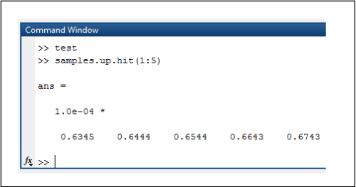
Figure 1. MATLAB data collection example using test.m.
System Architecture
Data collection using this framework requires a host PC capable of running MATLAB and a target embedded system with a serial interface. The framework provided here specifically supports RS-232, but could easily be ported to support other interfaces (see Figure 2).

Figure 2. Host/target architecture.
The framework spans both the PC host and the embedded target. C code is compiled for the target embedded system as well as the host system. The current host implementation requires a Win32 platform, but this could be ported to another OS such as Linux®.
The embedded target hardware must provide a serial interface of some kind. The current framework implementation supports UART but is designed to be portable to other transports. The target microcontroller must have enough resources to support the framework data and code requirements but also enough throughput to move data without excessively impacting the performance of the embedded system. An RTOS is not required by the framework, but it does not preclude the use of one.
The current framework implementation was developed with a 96MHz Cortex-M4 processor and could move data across the UART at near maximum throughput with little processor overhead. Smaller systems might require adjustments to the framework to work acceptably.
Figure 3 depicts the software components on both the host and the target. Components in blue are C-language modules that run on the host. Components in red are C-language modules that run on the target. Components in green are common to both domains. MATLAB scripts, in purple, are standard m-scripts that interface with an application-specific interface. The embedded framework implementation described here is built to run on the MAX35103EVKIT2 EV kit software, an ultrasonic water-flow measurement platform.
Components in grey are external platform-specific components.

Figure 3. System architecture.
C/C++ and 4GL languages that can interface with Win32 DLLs, like C# or Python, are supported using the "Win32 DLL I/F" module. This allows for easy support of a custom host application that might not require MATLAB.
The "COM" module implements the base host/target protocol. This is where the data packet definitions specific to the embedded application are found. The "Serialize" module implements escape-based packetization of binary data. Both modules are easily portable using callbacks that interface with communication APIs (host) or embedded peripherals (embedded target).
The definitions in the "COM" module drive the implementations in the "Host-Side Protocol" and the "Device-Side Protocol" components. These implementations are where commands/responses specific to the host and target are implemented and generally have a lot of commonality.
The following sections detail each major architectural module from top to bottom beginning with the host.
PC Host Architecture
The host side of the architecture depicted in Figure 2 consists primarily of MATLAB and OS-specific interfaces, and is described in detail in the following sections.
MATLAB Scripts
At the top of the host stack are the MATLAB scripts that perform application specific data collection and control. The script test.m, show in Code Listing 1, is a simple example of how to use the MATLAB MEX interface to open, set parameters, and collect data from the MAX35103EVKIT2 EV kit software.
h_flow = svflow('open',6);

if( h_flow )

     svflow('start',h_flow,100);

     samples = flow('get_samples',h_flow,1000);

     svflow('stop',h_flow);

     svflow('close',h_flow);

     clear h_flow;

     plot(samples.timestamp,samples.toff_diff)

     hold on

     transit = (samples.up.average + samples.down.average) ./ 2

     yyaxis right

     plot(samples.timestamp,transit)

     hold off

else

     error('failed to open com port');

end
Code Listing 1. test.m.
Only one public function can exist in a MEX interface module. In this case, it is svflow(). This function is how MATLAB scripts call into the MEX module. The name of the function is arbitrary, but 'svflow' was chosen as the moniker for the overall host/target protocol as implemented on the MAX35103EVKIT2 EV kit software (a water flow measurement platform).
The first argument to svflow() is a text string that indicates a subfunction to call. The second argument is the object handled referencing a specific flow object. This object is returned by svflow('open',...). This is the basic method that the framework uses to accommodate MEX while supporting an object-oriented architecture.
The test.m script in Code Listing 1, calls the subfunction 'open' to open COM6 on the Windows host machine. Next, 'start' is called to specify a sample rate of 100Hz and begin sample collection. 'get_samples' is then called to collect 1000 samples at the defined sampling rate. When this synchronous collection is complete, the flow object is stopped and closed. The MATLAB plot() function is used to display the data set and derived data.
MATLAB MEX Interface
The MATLAB MEX interface component for the MAX35103EVKIT2 EV kit software is implemented in a set of C-language files. It has access to internal MATLAB functions and exposes a standard interface that MATLAB scripts can call. All MEX-specific functionality is contained in mex.c, which provides a MATLAB-specific wrapper to the core protocol functionality implemented in flow.c that also serves as the Win32 DLL interface and serialize.c/com.c that are common to the host and the embedded target.
The module is created by using the MATLAB mex() function. The compile.m script in Code Listing 2 compiles the host C files into a form usable by MATLAB. The output of this command is the MATLAB MEX executable file. MATLAB must have been previously configured to use a native toolchain. Go to The Mathworks website for information about how to set up a toolchain for compiling MEX modules.
mex -g -output svflow -I'dll' -I'..' dll/mex.c dll/svflow.c ../serialize.c ../com.c
Code Listing 2. compile.m.
The MATLAB MEX interface specific to the MAX35103EVKIT2 EV kit software are implemented in mex.c. MATLAB requires all MEX modules to implement the function mexFunction() as the sole interface to the functionality provided by the module. To provide a way for a single MEX module to provide multiple object-oriented member functions, a subfunction mechanism is used. In Code Listing 3, mexFunction() references a function call table is used to dispatch subfunctions. The call table itself is shown in Code Listing 4.
for (i = 0; i < ARRAY_COUNT(s_function_table); i++)

{

     if (!lstrcmpA(s_function_table[i].p_name, func))

     {

         s_function_table[i].p_func(nlhs, p_lhs, nrhs - 1, p_rhs + 1);

        return;

     }

}
Code Listing 3. mexFunction() subfunction dispatch.
static const function_table_t s_function_table[] =

{

      { "get_samples", mex_get_samples },

      { "open", mex_open },

      { "close", mex_close },

       { "start", mex_start },

      { "stop", mex_stop }

};
Code Listing 4. subfunction call table.
The mex_* functions referenced in the call table are thin wrappers to the Win32 DLL functions detailed in the next section.
The MATLAB MEX interface also formats the data received by the embedded target in a form compatible with the double-matrix-oriented nature of MATLAB. The top-level object returned by the MATLAB MEX Interface is a MATLAB struct with the following fields:
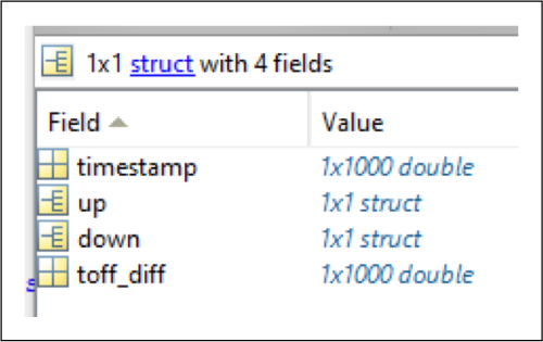
Figure 4. Top-level MATLAB data object.
The size of the double arrays timestamp and toff_diff is variable.
The up and down members are MATLAB structs with the following format:
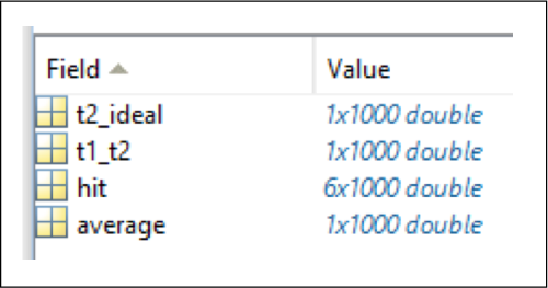
Figure 5. MATLAB struct containing MAX35013 time measurements.
Again, the length of each array is variable. This data corresponds directly with the data output by the MAX35103 on the MAX35103EVKIT2 evaluation board.
In mex.c, the function mex_get_samples() formats the data received by the embedded target using MATLAB mx* functions.
static void mex_get_samples(int nlhs, mxArray *p_lhs[], int nrhs, const mxArray *p_rhs[])

{

        char * sample_fieldnames[] =

       {

                "timestamp",

                 "up",

               "down",

                "toff_diff"

       };

        svflow_sample_t sample;

         void **pp = (void*)mxGetData(p_rhs[0]);
uint32_t sample_count = (uint32_t)mxGetScalar(p_rhs[1]);

         mxArray *p_sample_struct = mxCreateStructMatrix( 1, 1, ARRAY_COUNT(sample_fieldnames), sample_fieldnames );

      mxArray *p_timestamp = mxCreateNumericMatrix( 1, sample_count, mxDOUBLE_CLASS, mxREAL );

         mxSetField( p_sample_struct, 0, "timestamp", p_timestamp );

       mxSetField( p_sample_struct, 0, "up", create_direction_struct( sample_count, &sample.up ) );

        mxSetField( p_sample_struct, 0, "down", create_direction_struct( sample_count, &sample.down ) );

      mxArray *p_toff_diff = mxCreateNumericMatrix( 1, sample_count, mxDOUBLE_CLASS, mxREAL );

     mxSetField( p_sample_struct, 0, "toff_diff", p_toff_diff );

       sample.p_timestamp = (double_t*)mxGetData( p_timestamp );

       sample.p_tof_diff = (double_t*)mxGetData( p_toff_diff );

       svflow_get_samples( *pp, &sample, sample_count );

       p_lhs[0] = p_sample_struct;

}
Code Listing 5. mex_get_samples() in mex.c.
The 'up' and 'down' struct members are constructed in the create_direction_struct() function in mex.c.
Win32 DLL Interface
The Win32 DLL interface is implemented in svflow.c, which also contains the much of the protocol and platform specific code. The source code package associated with this app note contains a Visual Studio® project that can be used to build the DLL. However, MATLAB does not require the DLL. It is provided simply to aid those interested in writing custom data-analysis code in a language that can interface with DLLs.
Code Listing 6 below shows the DLL-interface function supported by the MAX35103EVKIT2 EV kit software. The functions correspond exactly to the subfunctions called in the MATLAB script shown in Code Listing 1.
void* svflow_open( uint32_t comport);

void svflow_close(void *pv_context);

uint32_t svflow_get_samples(void *pv_context, flow_sample_t

*p_flow_sample, uint32_t sample_count);

void svflow_start( void *pv_context, float_t sample_rate_hz );

void svflow_stop( void *pv_context );
Code Listing 6.- flow.h.
svflow_open ()returns an opaque flow communications context object associated with the given Win32 COM port or NULL if an error occurred.
svflow_close() closes communications and frees resources using the context object returned by svflow_open().
svflow_start() tells the embedded target to begin collecting flow samples at the specified sampling rate.
svflow_stop() tells the embedded target to end data collection.
While these functions are specific to the MAX35103EVKIT2 EV kit software, they could easily be replaced by functions appropriate to other embedded applications.
Host Protocol
The protocol used by the host and the embedded target are built on common definitions and functions in com.c/h and serialize.c/h. Protocols supported by the architecture generally consist of command/response and indication events. The host protocol is implemented in svflow.c with dependences on com.c and serialize.c, which are common to the host and the embedded target.
The host-side protocol uses com_* functions to issue commands and decode responses and indications. For example, in Code Listing 6, com_tx() is used to send a 'com_host_start_sampling_t' command packet to the embedded target.
It is important to note that all protocol functions are singled-threaded blocking calls.
void svflow_start( void *pv_context, float_t sample_rate_hz )

{

        context_t *p_context = (context_t*)pv_context;

       if( p_context )

       {

        com_host_start_sampling_t cmd;

         cmd.sample_rate_hz = sample_rate_hz;

          com_tx( &p_context->com, &cmd, COM_ID_HOST_START_SAMPLING,

           sizeof( com_host_start_sampling_t ) );

       }

    }
Code Listing 7. flow_start() in flow.c.
The host protocol module also defines data types that correspond with data types that transit the communications link, but are not identical to them. This difference allows some useful decoupling of the data types required by this module and the modules above. Specifically, it decouples the packet format (concise, single precision floats) from the data format used to accommodate MATLAB (verbose, matrix-oriented doubles). This means that translation code must exist in flow.c as can be seen in the serialize callback function in Code Listing 7.
static bool serialize_cb(void *pv_context, const void *pv_data, uint16_t length)

{

      context t * p_context = (context_t *)pv_context;

       const com_union_t *p_packet = (const com_union_t*)pv_data;

       if (p_packet->hdr.id == COM_ID_DEVICE_FLOW_SAMPLE )

     {

       com_device_flow_sample_t *p_com_sample =

              (com_device_flow_sample_t*)&p_packet->flow_sample;

        if (!p_context->sample_ndx )

        {

          p_context->time_offset = p_com_sample->timestamp;

      }

            svflow_sample_t *p_flow_sample = p_context>p_flow_sample;

         uint32_t ndx = p_context->sample_ndx;

          direction( &p_flow_sample->up, &p_com_sample->up, ndx );

           direction( &p_flow_sample->down, &p_com_sample->down, ndx );

         p_flow_sample->p_timestamp[ndx] = ( (double_t)( p_com_sample->timestamp –

           p_context->time_offset ) ) / 96000000.0;

         p_flow_sample->p_tof_diff[ndx] = p_com_sample->tof_diff;

           p_context->sample_ndx++;

        if( p_context->sample_ndx >= p_context->sample_count )

       return true;

     }

     return false;

}
Code Listing 8. Data translation in flow.c.
svflow.c also contains initialization and callback functions required to use comports on a Win32 platform as seen in Code Listing 8.
static uint16_t uart_write(com_t *p_com, void *pv, uint16_t length)

{

       DWORD written;

       context_t *p_context = (context_t*)p_com;

        WriteFile(p_context->hComm, pv, length, &written, NULL);

        return (uint16_t)written;

}

static uint16_t uart_read(com_t *p_com, void *pv, uint16_t length)

{

        DWORD read;

         context_t *p_context = (context_t*)p_com;

         ReadFile(p_context->hComm, pv, length, &read, NULL);

        return (uint16_t)read;

}
Code Listing 9. Win32 serial port callbacks in flow.c.
The COM module implements the routines that abstract the serial transport. com_init() initializes the abstraction object and com_read() is called to deserialize and dispatch specific commands/responses and indications.
Embedded Target Architecture
The embedded target architecture is conceptually simple and mirrors the host-side architecture excluding the platform and MATLAB specific components.
The embedded application contains functions that support the host side svflow_* calls defined in svflow.c. These functions include callbacks and configuration specific to the MAX35103EVKIT2 and can be found in board.c.
Like the comport abstraction on the host side, the embedded target has serial-port callbacks as can be seen in Code Listing 9. The read callback calls a chip support library (CSL) function call to write length bytes to the UART. The return value is the number of bytes actually written. The read callback uses a CSL-function call to read all bytes currently available (up to length) on the port.
static uint16_t uart_write(com_t * p_com, void * pv, uint16_t length)

{

         return UART_Write(MXC_UART0, (uint8_t *)pv, length);

}

static uint16_t uart_read(com_t * p_com, void * pv, uint16_t length)

{

       return UART_Read(MXC_UART0, (uint8_t *)pv, length, NULL);

}
Code Listing 10. Serial port callbacks in main.c.
The COM module is used by the embedded target to dispatch commands from the host. com_read() is called from the main plication loop and commands are dispatched in serialize_cb(), which is listed in Code Listing 10.
main.c contains the entirety of the embedded application for flow measurement on the MAX35103EVKIT2 EV kit software and uses the max3510x.c module to interface with the MAX35103 chip. Board.c contains board specific initialization and interrupt dispatch code.
Although this example implementation is specific to the MAX35103EVKIT2 EV kit software, the COM and serialize modules are not platform specific and could be easily ported to most modern microcontrollers and board designs.
static bool serialize_cb(void *pv_context, const void *pv_packet, uint16_t length)

{

       const com_union_t *p_com = (const com_union_t*)pv_packet;

         switch( p_com->hdr.id )

        {

             case COM_ID_HOST_START_SAMPLING:

         {

          if( p_com->start_sampling.sample_rate_hz > 0.0F &&

          p_com->start_sampling.sample_rate_hz <= 200.0F )

       {

        s_sampling_underflow = 0;

         s_sampling_overrun = 0;

        s_sample_state = sample_state_idle;

          s_send_samples = true;

        SYS_SysTick_Config( (uint32_t)((float_t)SYS_SysTick_GetFreq() /

          p_com>start_sampling.sample_rate_hz), 1);

                }

        break;

         }

           case COM_ID_HOST_STOP_SAMPLING:{

        {

            SYS_SysTick_Config( (uint32_t)((float_t)SYS_SysTick_GetFreq() / 10.0F), 1);

           s_send_samples = false;

         break;

             }

      }

      return false;

}
Code Listing 11. Serialize_cb in main.c.
Software Package Contents
The target firmware and Windows® host software can be downloaded from the Maxim website. It is provided as a zip archive. Extract the archive to a convenient directory on your computer. Figure 6 shows the directory structure of the target firmware and host software implementation.

Figure 6. Software directory structure.
The root directory contains main()and the COM and Serialize modules. Additionally, transducer.c/h contains parameters specific to the ultrasonic transducers that come with the MAX35103EVKIT2 EV kit software.
The board directory contains a subdirectory for each board supported by the MATLAB example firmware application. Support for custom user boards could be added here.
The csl and MAX3510x directories contain code specific to the microcontroller and peripherals on the MAX35103EVKIT2 EV kit software.
The IAR directory contains the project files used to build and debug the firmware on the MAX35103EVKIT2 EV kit software. New project configurations could be added to support custom user boards. The easiest way to do this would be to copy the configuration and then modify it to suit the new target.
The host and dll directories contain all the source necessary to build the Win32 DLL and MEX interface modules. Also available are the MATLAB scripts to compile the MEX interface module alongside the test script detailed in Code Listing 1.
Building the Target Firmware
The MATLAB example firmware can be built using IAR ARM. The IAR project file is in the iar directory. Once you load the project, be sure to check that your debugger is configured correctly (see Figure 4). The microcontroller on the MAX35103EVKIT2 EV kit software can be programmed with any ARM JTAG adapter supported by IAR using the 10-pin ARM header (J1).

Figure 7. IAR debugger options.
Project.out is the firmware image created when the project is built.
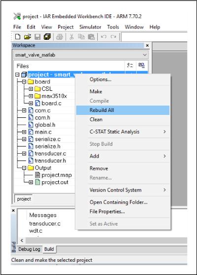
Figure 8. Building the firmware with IAR.
Building the Host Software
The MATLAB MEX interface can be built from within MATLAB using the compile.m script located in the host directory as depicted in Figure 6. The output of the build is flow.mexw64.
To use compile.m, you must have a MATLAB-supported C compiler installed. Go to The Mathworks website for details as this can change from one version of MATLAB to the next.
At the time of this writing, the free version of Microsoft Visual C++ can be used by MATLAB 2016a to generate MEX files.

Figure 9. Building the MEX interface.
The host software can also be built into a DLL module for use by non-MATLAB programs that know how to talk to DLLs. C# and Python applications (among others) can be supported in this way. The Microsoft Visual C++ project files to build a DLL can be found in the dll directory.
Hardware Configuration
The MAX35103EVKIT2 PCB must be connected to the ultrasonic flow body as described in the MAX35103EVKIT2 EV kit data sheet. Figure 10 shows the connections available on the MAX35103EVKIT2 PCB.
- POWER should be connected to a 6-24V AC or a DC source capable of supplying 200mA.
- VALVE can be left unconnected.
- PIEZO UP± should be connected to one of the flow body transducers
- PIEZO DOWN± should be connected to the other flow body transducer.
- RTD/THERMISTOR can be left unconnected.
The rotary switches are not used by the firmware.
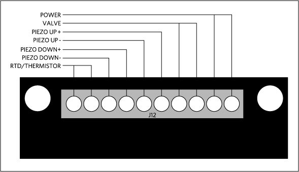
Figure 10. MAX35103EVKIT2 J12 pinout.
Conclusion
MATLAB provides a great platform for data analysis and algorithm development. This application note describes a simple, customizable software architecture that can be used to get the data into MATLAB without the cost and complexity of commercially available add-on modules.