简介
本应用笔记从多个方面解释与 ADE7912/ ADE7913所用Σ-Δ型调制器相关的数字滤波。滤波器的作用是抽取调制器输出以实现不同的采样速率,同时消除高频噪声。这些速率从最高8 kHz到最低1 kHz不等,允许用户根据微控制器处理带宽更新速率。
数字抽取滤波
功能描述
图1是ADE7912/ADE7913中实现的抽取滤波的框图。当芯片时钟设置为CLKIN = 4.096 MHz时,Σ-Δ调制器以1 MHz的频率提供一个位流。SINC4滤波器使用四个抽取比——32、64、128和256,以提供32 kHz、16 kHz、8 kHz和4 kHz输出。为了将带宽限制在有意义的频率,同时保持尽可能低的数据速率,使用一个衰减60 dB的额外低通滤波器(LPF)。这使得随后的有效值和功率计算更精确,从而减少微控制器必
须保留用于计量计算的带宽。

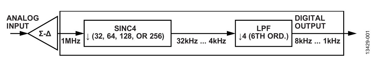 图1. ADE7912/ADE7913中实现的抽取滤波的框图
LPF再执行1/4抽取,并且有内部选项,可产生两个不同带宽。LPF实现为两个独立的六阶滤波器:一个滤波器提供较窄的带宽,一个滤波器提供较宽的带宽。
ADE7912/ADE7913提供多种输出数据速率(ODR):8 kHz、4 kHz、2 kHz和1 kHz,各种速率还有两个带宽可选(参见表1)。可选ODR有助于用户应对各种不同的情况,在微控制器实现的数据路径中做出自己的权衡。
表1. 用于获得不同ODR和带宽的CONFIG寄存器设置
| CONFIG寄存器 |
ODR (kHz) |
SINC4 + LPF带宽(kHz) |
| Bits[5:4] (ADC_FREQ) Setting |
Bit 7 (BW) Setting |
| 00 |
0 |
8 |
3.338 |
| 00 |
1 |
8 |
2.137 |
| 01 |
0 |
4 |
1.670 |
| 01 |
1 |
4 |
1.069 |
| 10 |
0 |
2 |
0.836 |
| 10 |
1 |
2 |
0.535 |
| 11 |
0 |
1 |
0.418 |
| 11 |
1 |
1 |
0.268 |
ODR和带宽通过CONFIG寄存器中的位7 (BW)和位[5:4] (ADC_FREQ)选择。表1显示了ADE7912/ADE7913时钟设置为CLKIN = 4.096 MHz时需要的不同BW和ADC_FREQ设置。带宽由增益衰减3 dB时的点表示。
SINC4 + LPF滤波器的频率响应和时间延迟特性
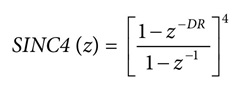
针对不同抽取速率(DR),SINC4的等效Z域公式如下所示:
与较窄带宽(CONFIG寄存器的位7 BW设置为1)对应的LPF Z域公式如下所示:

其中,LPF_BW1为对应较窄带宽的LPF。
与较宽带宽(CONFIG寄存器的位7 BW设置为0)对应的LPF Z域公式如下所示:
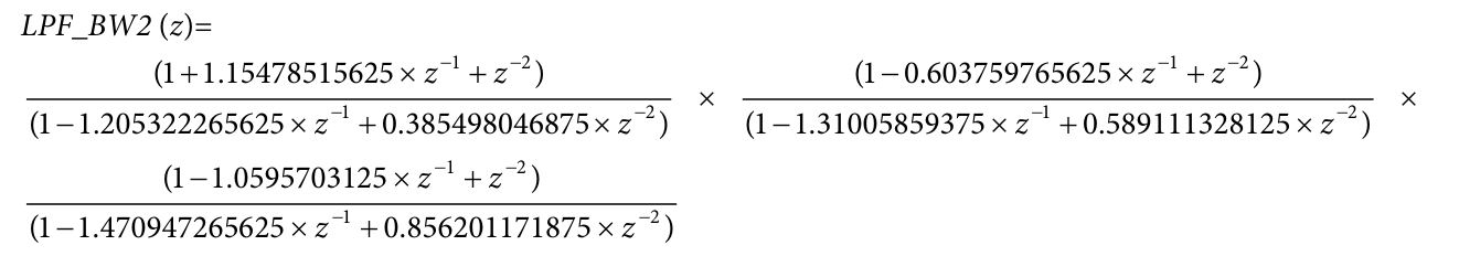
其中,LPF_BW2为对应较宽带宽的LPF。
不同滤波器的幅度频率响应和时间延迟
图2至图25和表2至表32提供了关于不同滤波器的幅度频率响应和在信号路径中引入的时间延迟的详细信息。输出数据速率(ODR)是指ADE7912/ADE7913模数转换器(ADC)的输出频率。滤波器的带宽(BW)为增益衰减3 dB时的频率。所有ODR和BW情况都显示了全频率响应或截止−3 dB点的响应,以及通带响应(从0 dB至−0.8 dB衰减)。
相位延迟定义通过滤波器的正弦信号相位响应延迟。表中给出了所有ODR和BW情况在不同频率时的相位延迟。
就功率计算而言,这些时间延迟不影响最终结果,因为电压和电流信号经历的传播时间延迟相同。然而,对于瞬变事件或与过零同时发生的事件,知道时间延迟可能很有用。
频率点的选择考虑到了以下要求:通过分段线性插值,可
以精确获得中间值。在需要幅度校正等情况下,这些频率点可能很有用。
ODR = 8 kHz且BW = 3.338 kHz


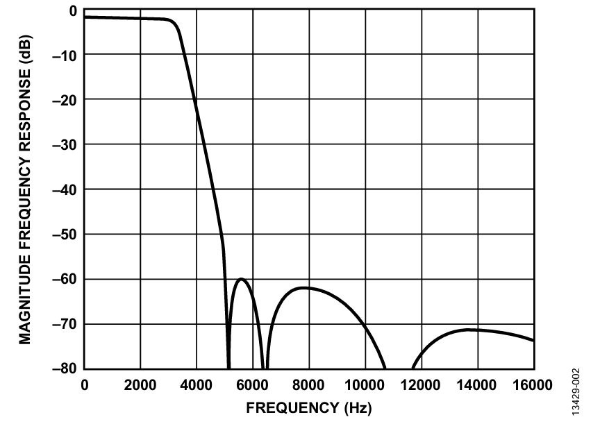 图2. ODR = 8 kHz且BW = 3.338 kHz时的全频率响应
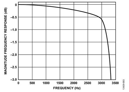

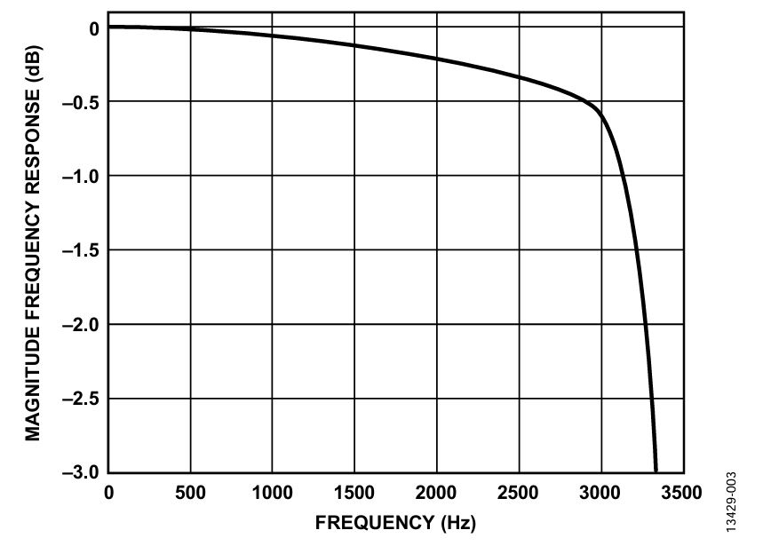 图3. ODR = 8 kHz且BW = 3.338 kHz时的3 dB点响应


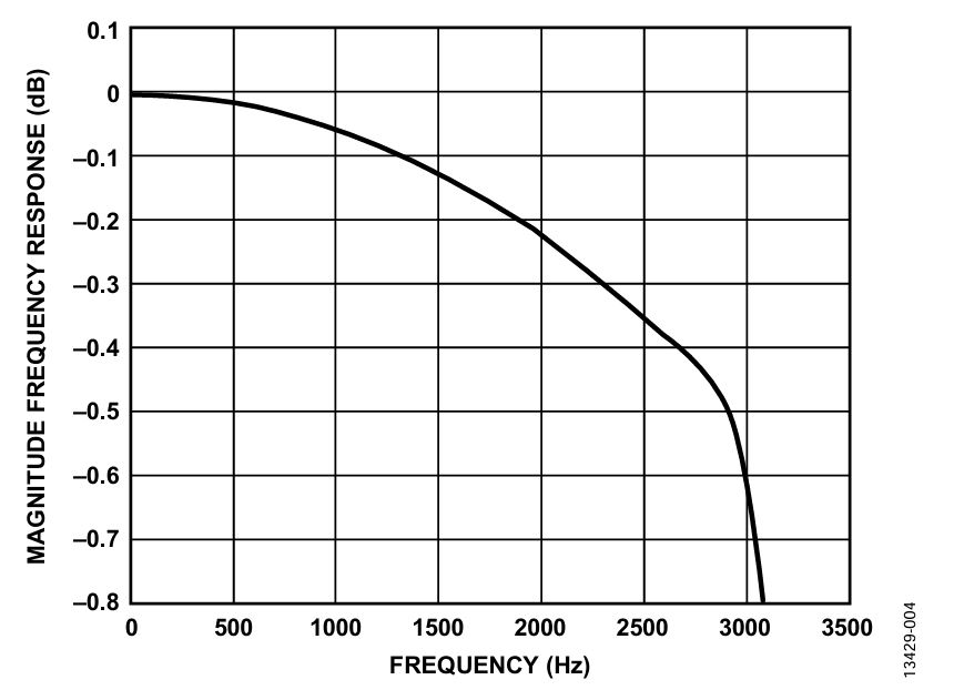 图4. ODR = 8 kHz且BW = 3.338 kHz时的平带响应
表2. 不同频率时的SINC4 + LPF增益响应,ODR = 8 kHz,BW = 3.338 kHz,频率范围 = 50 Hz至450 Hz
|
频率(Hz) |
| 50 |
100 |
150 |
200 |
250 |
300 |
350 |
400 |
450 |
| 幅度(milli_dB) |
0 |
−0.32 |
−0.87 |
−1.66 |
−2.67 |
−3.93 |
−5.44 |
−7.21 |
−9.26 |
表3. 不同频率时的SINC4 + LPF增益响应,ODR = 8 kHz,BW = 3.338 kHz,频率范围 = 500 Hz至900 Hz
|
频率(Hz) |
| 500 |
550 |
600 |
650 |
700 |
750 |
800 |
850 |
900 |
| 幅度(milli_dB) |
−11.6 |
−14.22 |
−17.15 |
−20.40 |
−23.97 |
−27.87 |
−32.11 |
−36.69 |
−41.61 |
表4. 不同频率时的SINC4 + LPF增益响应,ODR = 8 kHz,BW = 3.338 kHz,频率范围 = 950 Hz至1350 Hz
|
频率(Hz) |
| 950 |
1000 |
1050 |
1100 |
1150 |
1200 |
1250 |
1300 |
1350 |
| 幅度(milli_dB) |
−46.86 |
−52.45 |
−58.37 |
−64.6 |
−71.13 |
−77.95 |
−85.05 |
−92.41 |
−100 |
表5. 不同频率时的SINC4 + LPF增益响应,ODR = 8 kHz,BW = 3.338 kHz,频率范围 = 1400 Hz至2200 Hz
|
频率(Hz) |
| 1400 |
1500 |
1600 |
1700 |
1800 |
1900 |
2000 |
2100 |
2200 |
| 幅度(dB) |
−0.108 |
−0.124 |
−0.141 |
−0.159 |
−0.177 |
−0.197 |
−0.218 |
−0.241 |
−0.265 |
表6. 不同频率时的SINC4 + LPF增益响应,ODR = 8 kHz,BW = 3.338 kHz,频率范围 = 2300 Hz至3100 Hz
|
频率(Hz) |
| 2300 |
2400 |
2500 |
2600 |
2700 |
2800 |
2900 |
3000 |
3100 |
| 幅度(dB) |
−0.291 |
−0.318 |
−0.346 |
−0.374 |
−0.402 |
−0.434 |
−0.486 |
−0.6 |
−0.859 |
表7. 不同频率时的SINC4 + LPF增益响应,ODR = 8 kHz,BW = 3.338 kHz,频率范围 = 3200 Hz至3500 Hz
|
频率(Hz) |
| 3200 |
3300 |
3338 |
3400 |
3500 |
| 幅度(dB) |
−1.414 |
−2.452 |
−3.0 |
−4.09 |
−6.27 |
表8. 不同频率时的SINC4 + LPF相位延迟响应,ODR = 8 kHz,BW = 3.338 kHz
|
频率(Hz) |
| 50 |
500 |
750 |
1000 |
1500 |
2000 |
2500 |
3000 |
3300 |
| 相位延迟(μs) |
225 |
226 |
227 |
229 |
234 |
241 |
254 |
277 |
321 |
ODR = 8 kHz且BW = 2.137 kHz


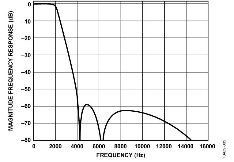 图5. ODR = 8 kHz且BW = 2.137 kHz时的全频率响应


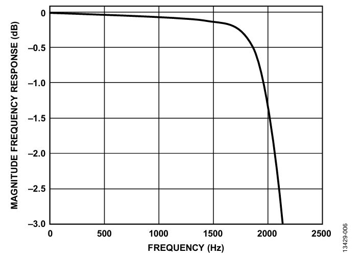 图6. ODR = 8 kHz且BW = 2.137 kHz时的3 dB点响应
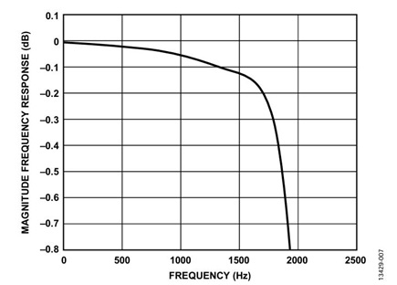

 图7. ODR = 8 kHz且BW = 2.137 kHz时的平带响应
表9. 不同频率时的SINC4 + LPF增益响应,ODR = 8 kHz,BW = 2.137 kHz,频率范围 = 50 Hz至450 Hz
|
频率(Hz) |
| 50 |
100 |
150 |
200 |
250 |
300 |
350 |
400 |
450 |
| 幅度(milli_dB) |
0 |
−0.56 |
−1.5 |
−2.77 |
−4.34 |
−6.19 |
−8.25 |
−10.51 |
−12.91 |
表10. 不同频率时的SINC4 + LPF增益响应,ODR = 8 kHz,BW = 2.137 kHz,频率范围 = 500 Hz至900 Hz
|
频率(Hz) |
| 500 |
550 |
600 |
650 |
700 |
750 |
800 |
850 |
900 |
| 幅度(milli_dB) |
−15.44 |
−18.08 |
−20.82 |
−23.68 |
−26.70 |
−29.90 |
−33.36 |
−37.13 |
−41.29 |
表11. 不同频率时的SINC4 + LPF增益响应,ODR = 8 kHz,BW = 2.137 kHz,频率范围 = 950 Hz至1400 Hz
|
频率(Hz) |
| 950 |
1000 |
1050 |
1100 |
1150 |
1200 |
1250 |
1300 |
1400 |
| 幅度(milli_dB) |
−45.90 |
−51.01 |
−56.64 |
−62.8 |
−69.41 |
−76.40 |
−83.64 |
−90.96 |
−105 |
表12. 不同频率时的SINC4 + LPF增益响应,ODR = 8 kHz,BW = 2.137 kHz,频率范围 = 1500 Hz至2200 Hz
|
频率(Hz) |
| 1500 |
1600 |
1700 |
1800 |
1900 |
2000 |
2100 |
2137 |
2200 |
| 幅度(dB) |
−0.119 |
−0.140 |
−0.188 |
−0.314 |
−0.621 |
−1.274 |
−2.243 |
−3.01 |
−4.167 |
表13. 不同频率时的SINC4 + LPF相位延迟响应,ODR = 8 kHz,BW = 2.137 kHz
|
频率(Hz) |
| 50 |
500 |
750 |
1000 |
1500 |
1750 |
2000 |
2100 |
| 相位延迟(μs) |
294 |
296 |
299 |
304 |
322 |
338 |
365 |
377 |
ODR = 4 kHz且BW = 1.67 kHz


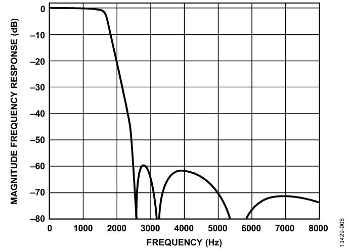 图8. ODR = 4 kHz且BW = 1.67 kHz时的全频率响应
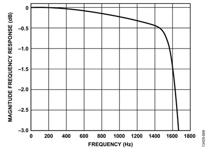

 图9. ODR = 4 kHz且BW = 1.67 kHz时的3 dB点响应
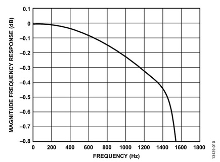

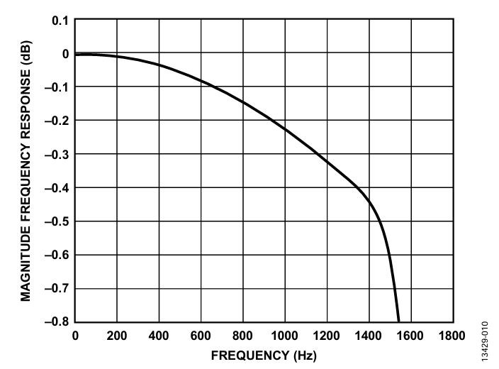 图10. ODR = 4 kHz且BW = 1.67 kHz时的平带响应
表14. 不同频率时的SINC4 + LPF增益响应,ODR = 4 kHz,BW = 1.67 kHz,频率范围 = 50 Hz至450 Hz
|
频率(Hz) |
| 50 |
100 |
150 |
200 |
250 |
300 |
350 |
400 |
450 |
| 幅度(milli_dB) |
0 |
−1.323 |
−3.589 |
−6.865 |
−11.234 |
−16.784 |
−23.596 |
−31.732 |
−41.222 |
表15. 不同频率时的SINC4 + LPF增益响应,ODR = 4 kHz,BW = 1.67 kHz,频率范围 = 500 Hz至900 Hz
|
频率(Hz) |
| 500 |
550 |
600 |
650 |
700 |
750 |
800 |
850 |
900 |
| 幅度(milli_dB) |
−52.06 |
−64.199 |
−77.554 |
−92.011 |
−107.44 |
−123.73 |
−140.81 |
−158.66 |
−177.37 |
表16. 不同频率时的SINC4 + LPF增益响应,ODR = 4 kHz,BW = 1.67 kHz,频率范围 = 950 Hz至1350 Hz
|
频率(Hz) |
| 950 |
1000 |
1050 |
1100 |
1150 |
1200 |
1250 |
1300 |
1350 |
| 幅度(dB) |
−0.197 |
−0.218 |
−0.240 |
−0.265 |
−0.291 |
−0.318 |
−0.346 |
−0.373 |
−0.401 |
表17. 不同频率时的SINC4 + LPF增益响应,ODR = 4 kHz,BW = 1.67 kHz,频率范围 = 1400 Hz至1900 Hz
|
频率(Hz) |
| 1400 |
1450 |
1500 |
1550 |
1600 |
1670 |
1700 |
1800 |
1900 |
| 幅度(dB) |
−0.433 |
−0.486 |
−0.598 |
−0.856 |
−1.407 |
−3.01 |
−4.071 |
−8.807 |
−14.39 |
表18. 不同频率时的SINC4 + LPF相位延迟响应,ODR = 4 kHz,BW = 1.67 kHz
|
频率(Hz) |
| 50 |
250 |
500 |
750 |
1000 |
1250 |
1500 |
1650 |
| 相位延迟(μs) |
450 |
452 |
458 |
467 |
483 |
508 |
555 |
608 |
ODR = 4 kHz且BW = 1.069 kHz
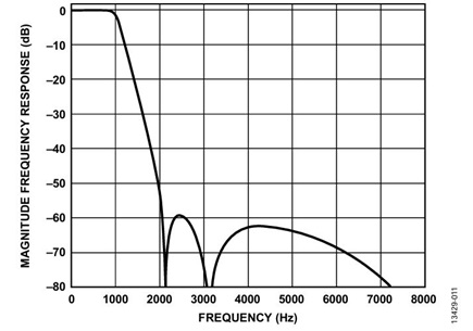

 图11. ODR = 4 kHz且BW = 1.069 kHz时的全频率响应
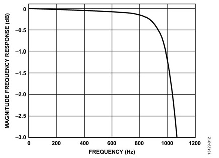

 图12. ODR = 4 kHz且BW = 1.069 kHz时的3 dB点响应
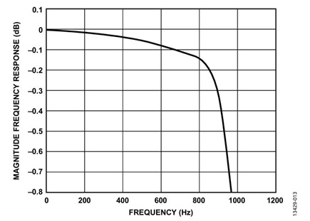

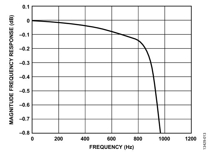 图13. ODR = 4 kHz且BW = 1.069 kHz时的平带响应
表19. 不同频率时的SINC4 + LPF增益响应,ODR = 4 kHz,BW = 1.069 kHz,频率范围 = 50 Hz至450 Hz
|
频率(Hz) |
| 50 |
100 |
150 |
200 |
250 |
300 |
350 |
400 |
450 |
| 幅度(milli_dB) |
0 |
−2.19 |
−5.60 |
−9.92 |
−14.85 |
−20.23 |
−26.10 |
−32.76 |
−40.68 |
表20. 不同频率时的SINC4 + LPF增益响应,ODR = 4 kHz,BW = 1.069 kHz,频率范围 = 500 Hz至900 Hz
|
频率(Hz) |
| 500 |
550 |
600 |
650 |
700 |
750 |
800 |
850 |
900 |
| 幅度(milli_dB) |
−50.39 |
−62.16 |
−75.77 |
−90.33 |
−104.7 |
−119.2 |
−139.8 |
−186.9 |
−311.5 |
表21. 不同频率时的SINC4 + LPF增益响应,ODR = 4 kHz,BW = 1.069 kHz,频率范围 = 950 Hz至1300 Hz
|
频率(Hz) |
| 950 |
1000 |
1050 |
1069 |
1100 |
1150 |
1200 |
1250 |
1300 |
| 幅度(dB) |
−0.617 |
−1.265 |
−2.423 |
−3.015 |
−4.147 |
−6.326 |
−8.776 |
−11.343 |
−13.936 |
表22. 不同频率时的SINC4 + LPF相位延迟响应,ODR = 4 kHz,BW = 1.069 kHz
|
频率(Hz) |
| 50 |
250 |
500 |
750 |
1000 |
1250 |
| 相位延迟(μs) |
588 |
593 |
609 |
643 |
730 |
795 |
ODR = 2 kHz且BW = 0.836 kHz
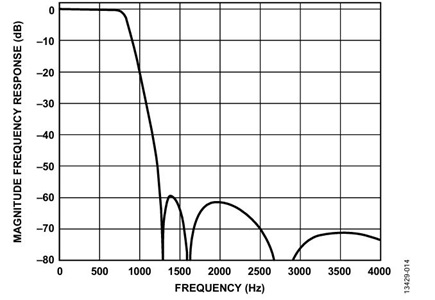

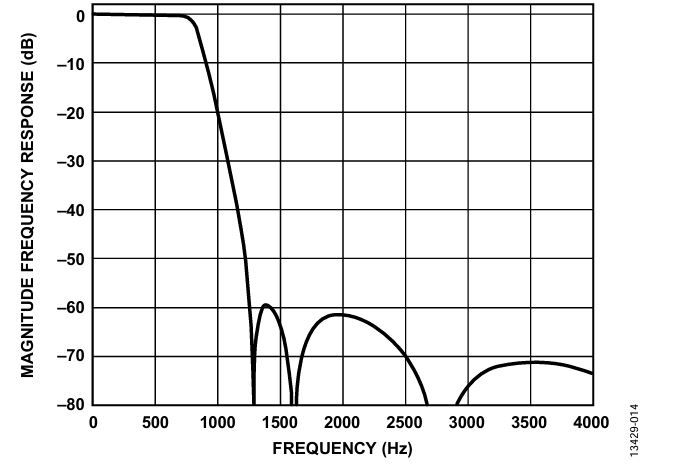 图14. ODR = 2 kHz且BW = 0.836 kHz时的全频率响应
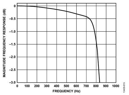

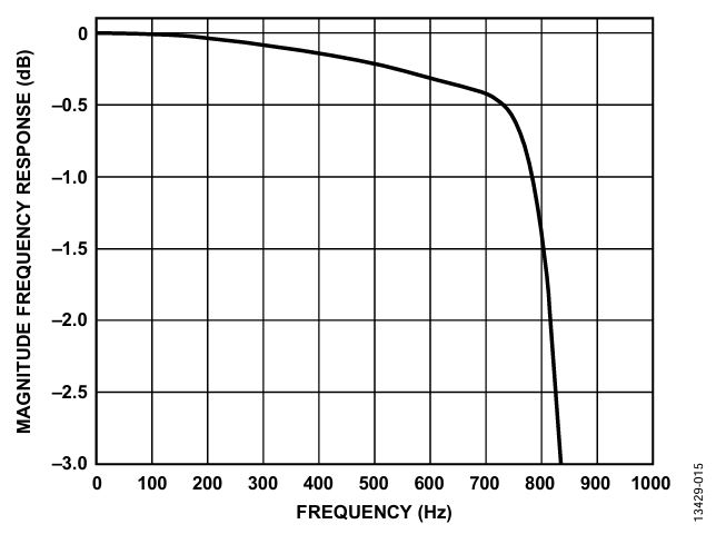 图15. ODR = 2 kHz且BW = 0.836 kHz时的3 dB点响应
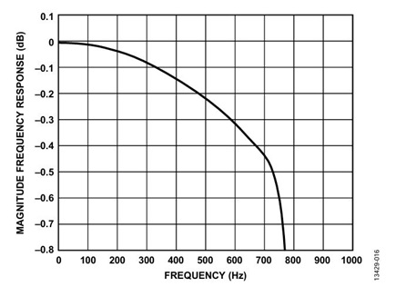

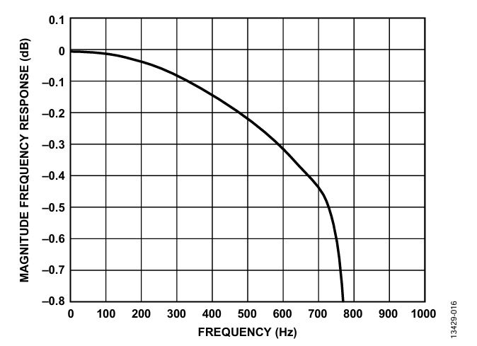 图16. ODR = 2 kHz且BW = 0.836 kHz时的平带响应
表23. 不同频率时的SINC4 + LPF增益响应,ODR = 2 kHz,BW = 0.836 kHz,频率范围 = 50 Hz至450 Hz
|
频率(Hz) |
| 50 |
100 |
150 |
200 |
250 |
300 |
350 |
400 |
450 |
| 幅度(milli_dB) |
0 |
−5.5 |
−15.37 |
−30.27 |
−50.55 |
−76 |
−106 |
−139 |
−176 |
表24. 不同频率时的SINC4 + LPF增益响应,ODR = 2 kHz,BW = 0.836 kHz,频率范围 = 500 Hz至1000 Hz
|
频率(Hz) |
| 500 |
550 |
600 |
650 |
700 |
750 |
800 |
836 |
850 |
900 |
950 |
1000 |
| 幅度(dB) |
−0.216 |
−0.263 |
−0.316 |
−0.372 |
−0.431 |
−0.594 |
−1.39 |
−3.05 |
−4.03 |
−8.75 |
−14.33 |
−20.0 |
表25. 不同频率时的SINC4 + LPF相位延迟响应,ODR = 2 kHz,BW = 0.836 kHz
|
频率(Hz) |
| 50 |
125 |
250 |
350 |
400 |
500 |
750 |
830 |
| 相位延迟(μs) |
901 |
904 |
915 |
930 |
939 |
965 |
1109 |
1223 |
ODR = 2 kHz且BW = 0.535 kHz


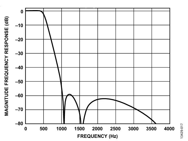 图17. ODR = 2 kHz且BW = 0.535 kHz时的全频率响应


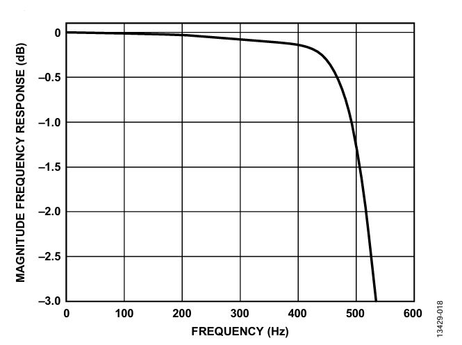 图18. ODR = 2 kHz且BW = 0.535 kHz时的3 dB点响应


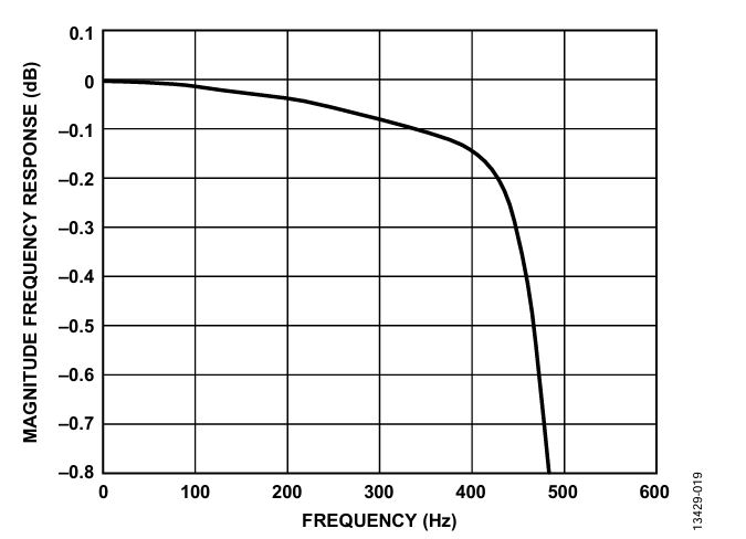 图19. ODR = 2 kHz且BW = 0.535 kHz时的平带响应
表26. 不同频率时的SINC4 + LPF增益响应,ODR = 2 kHz,BW = 0.535 kHz,频率范围 = 50 Hz至450 Hz
|
频率(Hz) |
| 50 |
100 |
150 |
200 |
250 |
300 |
350 |
400 |
450 |
| 幅度(milli_dB) |
0 |
−7.69 |
−17.99 |
−30.48 |
−48.05 |
−73.36 |
−102.34 |
−137.17 |
−305.62 |
表27. 不同频率时的SINC4 + LPF增益响应,ODR = 2 kHz,BW = 0.535 kHz,频率范围 = 500 Hz至750 Hz
|
频率(Hz) |
| 500 |
535 |
550 |
600 |
650 |
700 |
750 |
| 幅度(dB) |
−1.24 |
−3.01 |
−4.10 |
−8.72 |
−13.88 |
−19.01 |
−24.03 |
表28. 不同频率时的SINC4 + LPF相位延迟响应,ODR = 2 kHz,BW = 0.535 kHz
|
频率(Hz) |
| 50 |
125 |
250 |
350 |
400 |
500 |
535 |
| 相位延迟(μs) |
1177 |
1185 |
1217 |
1268 |
1309 |
1459 |
1525 |
ODR = 1 kHz且BW = 0.418 kHz


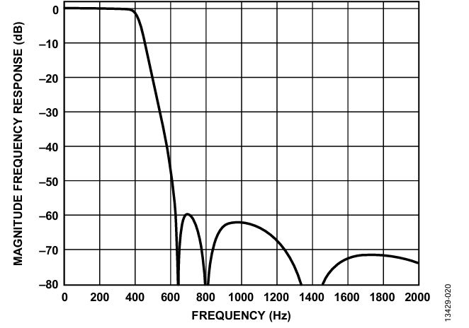 图20. ODR = 1 kHz且BW = 0.418 kHz时的全频率响应


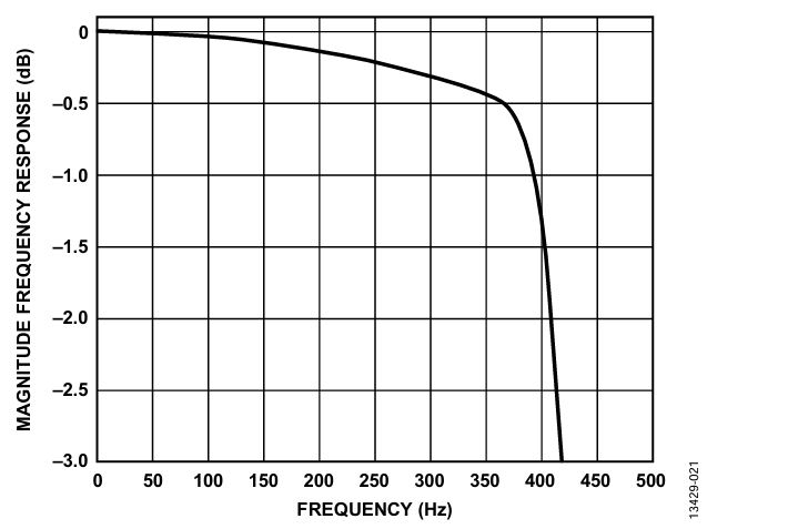 图21. ODR = 1 kHz且BW = 0.418 kHz时的3 dB点响应
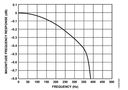

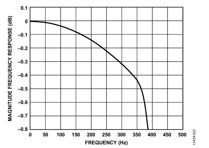 图22. ODR = 1 kHz且BW = 0.418 kHz时的平带响应
表29. 不同频率时的SINC4 + LPF增益响应,ODR = 1 kHz,BW = 0.418 kHz,频率范围 = 50 Hz至600 Hz
|
频率(Hz) |
| 50 |
100 |
150 |
200 |
250 |
300 |
350 |
400 |
418 |
450 |
500 |
550 |
600 |
| 幅度(dB) |
0 |
−0.024 |
−0.070 |
−0.133 |
−0.210 |
−0.310 |
−0.424 |
−1.355 |
−2.98 |
−8.64 |
−19.95 |
−31.74 |
−45.78 |
表30. 不同频率时的SINC4 + LPF相位延迟响应,ODR = 1 kHz,BW = 0.418 kHz
|
频率(Hz) |
| 50 |
100 |
150 |
200 |
250 |
300 |
350 |
400 |
| 相位延迟(μs) |
1806 |
1820 |
1843 |
1879 |
1930 |
2005 |
2122 |
2349 |
ODR = 1 kHz且BW = 0.268 kHz
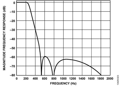

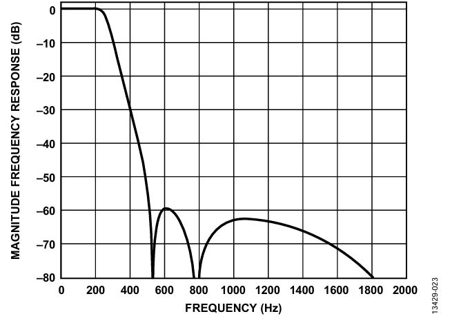 图23. ODR = 1 kHz且BW = 0.268 kHz时的全频率响应
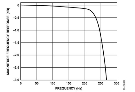

 图24. ODR = 1 kHz且BW = 0.268 kHz时的3 dB点响应
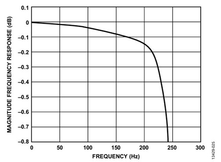

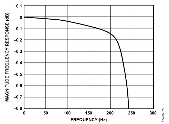 图25. ODR = 1 kHz且BW = 0.268 kHz时的平带响应
表31. 不同频率时的SINC4 + LPF增益响应,ODR = 1 kHz,BW = 0.268 kHz,频率范围 = 50 Hz至400 Hz
|
频率(Hz) |
| 50 |
100 |
150 |
200 |
250 |
268 |
300 |
350 |
400 |
| 幅度(dB) |
0 |
−0.022 |
−0.065 |
−0.128 |
−1.20 |
−3.0 |
−8.615 |
−18.9 |
−28.91 |
表32. 不同频率时的SINC4 + LPF相位延迟响应,ODR = 1 kHz,BW = 0.268 kHz
|
频率(Hz) |
| 50 |
100 |
150 |
200 |
250 |
| 相位延迟(μs) |
2363 |
2402 |
2477 |
2615 |
2913 |


