AN-1146: ADIS16334 Mounting/Mechanical Design Guidelines and Examples
Introduction
The ADIS16334 is a low profile, fully calibrated, MEMS inertial measurement units (IMU). Figure 1 provides a top view of this package, which provides four mounting holes, with recessed mounting shelves that help manage the overall height of the attachment hardware. The mounting holes provide enough clearance for M2 × 0.4 mm or 2 to 56 machine screws.

Figure 1. ADIS16334AMLZ, Top View.
Figure 2 provides a bottom view of this package. Notice that the substrate, which supports the internal sensors, extends beyond the bottom of the aluminum housing.
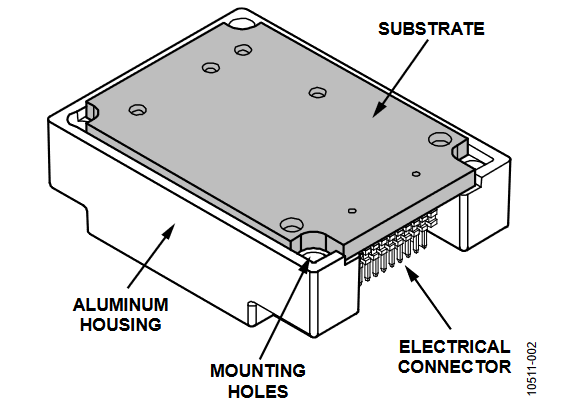
Figure 2. ADIS16334AMLZ, Bottom View.
Mating Connector
The electrical connector is a dual-row, 1 mm pitch header that has 20 conductors. ADIS16334 evaluation tools use a part from Samtec’s CLM-110-2 family, as the mating connector. Refer to the ADIS16334 data sheet for more details.
Connector-up Mounting
Figure 3 provides an example of using a connector-up mounting approach. Figure 4 provides some mechanical design information for this approach when using the flexible cable that comes with the ADIS16334/PCBZ.

Figure 3. Connector-Up Example.
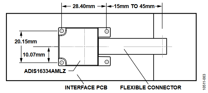
Figure 4. Connector-Up Mounting Example.
Connector-down Mounting
Connector-down mounting methods eliminate the need for a special flexible cable but require consideration of two additional features: the mounting bracket and the mounting surface. The example in Figure 5 uses a special mounting bracket that protects the substrate and spreads the mounting force across the bottom of the aluminum lid. Figure 6 and Figure 7 provide more details on the bracket design, which fits the edge of the aluminum housing and protects the substrate. Figure 8 provides a continuous printed circuit board (PCB) design example, while Figure 9, Figure 10, and Figure 11 provide an example design for mounting this to a system bulkhead.

Figure 5. Connector-Down Mounting Example.

Figure 6. ADIS1633x/BRACKET, Physical Features.
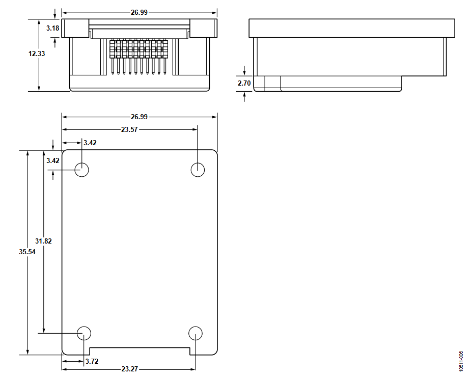
Figure 7. ADIS1633x/BRACKET, Design Details.

Figure 8. Connector-Down, Continuous PCB Mechanical Design.

Figure 9. Connector-Down, Bulkhead Mounting Example.

Figure 10. Bulkhead Mechanical Design Example.

Figure 11. PCB Interface Design Example.
作者
