AN-1099: ADI公司LDO电容选型指南
为什么电容的选择至关重要?
电容往往被人们所忽视。电容既没有数十亿计的晶体管,也没有采用最新的亚微米制造工艺。在许多工程师的心目中,电容不过是两个导体加上中间的隔离电解质。总而言之,它们属于最低级的电子元件之一。
工程师们通常通过添加一些电容的办法来解决噪声问题。这是因为他们普遍将电容视为解决噪声相关问题的“灵丹妙药”,很少考虑电容和额定电压以外的参数。但是,和其他电子元器件一样,电容也有缺陷,例如寄生电容、电感、电容温漂和电压偏移等非理想特性。
为许多旁路应用或电容实际容值非常重要的应用选择电容时,必须考虑上述这些因素。电容选择不当可能会导致电路不稳定,噪声或功耗过大,产品寿命缩短,以及电路行为不可预测等现象
电容技术
电容具有各种尺寸、额定电压和其它特性,能够满足不同应用的具体要求。常用电介质材料包括油、纸、玻璃、空气、云母、各种聚合物薄膜和金属氧化物。每一种电解质都具有一系列特定属性,可满足每种应用的独特需求。
在稳压器中,有三大类电容通常用作电压输入和输出旁路电容:多层陶瓷电容、固态钽电解电容和铝电解电容。
多层陶瓷电容
多层陶瓷电容(MLCC)同时具有小型、有效串联电阻和电感(ESR和ESL)低、工作温度范围宽的优点,通常是作为旁路电容的首选。
它并非无可挑剔。根据所用的电介质材料,电容可能随温度变化和交直流偏置发生大幅偏移。此外,因为在许多陶瓷电容中介质材料具有压电性,振动或机械冲击可能会转化为电容上的交流噪声电压。在大部分情况下,此噪声一般处于微伏范围内。但在极端情况下,可能会产生毫伏级的噪声。
VCO、PLL、RF PA以及低电平模拟信号链等应用对电源轨上的噪声非常敏感。这种噪声在VCO和PLL中表现为相位噪声,而在RF PA中则为载波振幅调制。在EEG、超声波和CAT扫描前置放大器等低电平信号链应用中,噪声会导致在这些仪器的输出中出现杂散噪声。在所有这些噪声敏感应用中,必须认真评估多层陶瓷电容。
选择陶瓷电容时是否考虑温度和电压效应非常重要。多层陶瓷电容选型部分谈到了根据公差和直流偏置特性来确定某个电容的最小电容值的过程。
虽然陶瓷电容仍有缺点,但对于许多应用都能够实现尺寸最小、性价比最高的解决方案,因此在当今几乎每一类电子设备上都能看到它们的身影。
固态钽电解电容
固态钽电解电容单位体积电容最高(CV乘积)。只有双层或超级电容才具有更高的CV乘积。
在1 μF范围内,陶瓷电容仍然更小且ESR低于钽电容,但固态钽电容不太会受到温度、偏置电压或震动效应的影响。钽电容比陶瓷电容贵好几倍,但在无法容忍压电效应的低噪声应用中,钽电容常常是唯一可行的选择。
市面上的传统低容值固态钽电容所用外壳往往一般较小,故等效串联电阻(ESR)较高。大容值(>68 μF)钽电容可具有低于1 Ω的ESR,但一般体积较大。
最近市场上出现了一种新钽电容,它使用导电聚合物电解质代替普通的二氧化锰固态电解质。过去,固态钽电容浪涌电流能力有限,需要一个串联电阻将浪涌电流限制在安全值内。导电聚合物钽电容不会受到浪涌电流限制。这项技术的另一好处是电容ESR更低。
任何钽电容的泄漏电流比等值陶瓷电容大好几倍,可能不适合超低电流应用。
例如,在85°C工作温度下,1 μF/25 V钽电容在额定电压下的最大泄漏电流为2.5 μA。/p>
多家厂商提供0805外壳、1 μF/25 V、500 mΩ ESR的导电聚合物钽电容。虽然比0402或0603外壳的典型1 μF陶瓷电容更大一些,但0805在RF和PLL等以低噪声为主要设计目标的应用中,电容尺寸还是明显有所缩小。
因为固态钽电容的电容值可以相对于温度和偏置电压保持稳定的电容特性,因此选择标准仅包括容差、工作温度范围内的降压情况以及最大ESR。
固态聚合物电解质技术的一大缺点是,这类钽电容在无铅焊接工艺中更容易受高温影响。一般情况下,制造商会详细说明电容不得暴露于三个以上的焊接周期。如果在装配工艺中忽视这一要求,就会导致长期可靠性问题。
铝电解电容
传统的铝电解电容往往体积较大、ESR和ESL较高、漏电流相对较高且使用寿命有限(以数千小时计)。
OS-CON型电容是一种与固态聚合物钽电容有关的技术,实际上比钽电容早10年或更早就问世了。它们采用有机半导体电解质和铝箔阴极,以实现较低的ESR。因为不存在液态电解质逐渐变干的问题,OS-CON型电容的使用寿命比传统铝电解电容有了很大的提高。
目前市面的OS-CON型电容可承受125°C高温,但大多数仍停留在105°C。
虽然OS-CON型电容的性能比传统的铝电解电容明显改善,但是与陶瓷电容或固态聚合物钽电容相比,往往体积更大、ESR更高。与固态聚合物钽电容一样,它们不受压电效应影响,适合要求低噪声的应用场合。
多层陶瓷电容选型
输出电容
ADI公司LDO设计采用节省空间的小型陶瓷电容工作,但只要考虑ESR值,它们便可以采用大多数常用电容。输出电容的ESR会影响LDO控制环路的稳定性。为了确保LDO稳定工作,推荐使用至少1 μF、ESR为1 Ω或更小的电容。
输出电容还会影响负载电流变化的瞬态响应。采用较大的输出电容值可以改善LDO对大负载电流变化的瞬态响应。图1至3所示为输出电容值分别为1 μF、10 μF和20 μF的ADP151的瞬态响应。

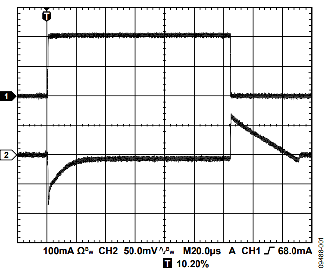

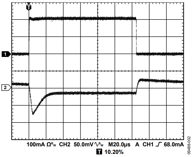

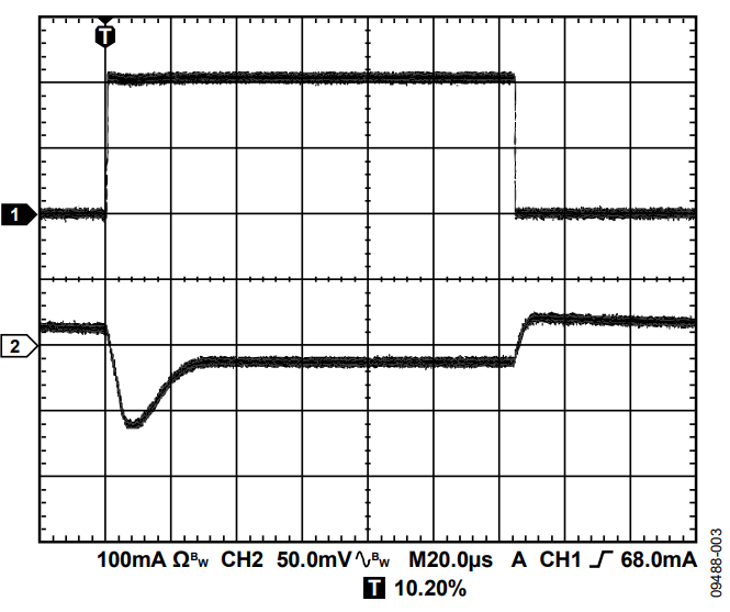
因为LDO控制环路的带宽有限,因此输出电容必须提供快速瞬变所需的大多数负载电流。1 μF电容无法持续很长时间供应电流,会产生约80 mV的负载瞬变。10 μF电容将负载瞬变降低至约70 mV。将输出电容提高至20 μF,LDO控制回路就能快速响应并主动降低负载瞬变。测试条件如表1所示。
| 条件 | 值 |
| UUT | ADP151-3.3 |
| VOUT | 3.3 V |
| VIN | 5 V |
| 负载瞬变 | 1 mA至200 mA,500 mA/µs |
| 通道1 | 负载电流 |
| 通道2 | VOUT (交流耦合) |
输入旁路电容
在VIN和GND之间连接一个1 µF电容可以降低电路对PCB布局的敏感性,特别是在长输入走线或高源阻抗的情况下。如果要求输出电容大于1 μF,应选用更高的输入电容。
输入和输出电容特性
只要符合最小电容和最大ESR要求,LDO可以采用任何质量良好的电容。陶瓷电容可采用各种各样的电介质制造,温度和所施加的电压不同时其特性也不相同。电容必须具有足以在工作温度范围和直流偏置条件下确保最小电容的电介质。建议在5V应用中使用电压额定值为6.3 V或10 V的X5R或X7R电介质。Y5V和Z5U电介质的温度和直流偏置特性不佳,建议不要使用。
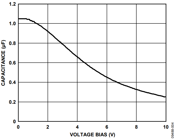
图4所示为0402、1 μF、10 V、X5R电容的电容与电压偏置特性关系图。电容的电压稳定性受电容封装尺寸和电压额定值影响极大。一般来说,封装较大或电压额定值较高的电容具有更好的电压稳定性。X5R电介质的温度变化率在−40°C至+85°C温度范围内约为±15%,与封装或电压额定值没有函数关系。

考虑电容随温度、元件容差和电压的变化时,可以利用公式1确定最差情况下的电容。
CEFF = CBIAS × (1 − TVAR) × (1 − TOL)
其中:
CBIAS是工作电压下的有效电容。
TVAR为最差情况下电容随温度的变化量(几分之一)。
TOL为最差情况下的元件容差(几分之一)。
本例中,假定X5R电介质在−40°C至+85°C范围内的最差情况电容(TVAR)为0.15(15%)。假设电容容差(TOL)为0.10 (10%),CBIAS在1.8 V下为0.94 μF,如图4所示。
将这些值代入公式1中可得到:
CEFF = 0.94 μF × (1 − 0.15) × (1 − 0.1) = 0.719 μF
在此示例中,LDO指定在期望工作电压和温度范围内的最小输出旁路电容为0.70 μF。因此,针对此应用所选的电容满足此要求。
结语
为了保证LDO的性能,必须了解并评估旁路电容的直流偏置、温度变化和容差对所选电容的影响。
此外,在要求低噪声、低漂移或高信号完整性的应用中,也必须认真考虑电容技术。所有电容都会受到非理想行为的影响,但一些电容技术比其他技术更适合于某些特定应用。
作者
