AN-1091: Configuring the AD7606/AD7607 for Slow Supply Ramp Conditions
Introduction
The AD7606/AD7606-6/AD7606-4/AD7607 are 16-/14-bit, simultaneous sampling, analog-to-digital data acquisition systems (DAS). The parts operate from a single 4.75 V to 5.25 V AVCC supply and a 2.3 V to 5.25 V digital interface supply, VDRIVE. This application note explains how to configure the AD7606/AD7607 to heighten application immunity when the ramp rate on the AVCCC and VDRIVE is very slow or the time between the ramps on these supplies is long.
Slow Supply Ramp Conditions
In multiboard systems where power supply circuitry is used to power multiple boards or on a board where there is heavy loading on the AVCC and VDRIVE supply generation circuitry, very long ramp rates may be seen at the AD7606/AD7607 AVCC and VDRIVE supply pins.
The AD7606/AD7607 mode of operation is controlled using pin programmable inputs. In an application, the pin programmable inputs can be hardwired to VDRIVE or AGND or can be driven by general-purpose input/output (GPIO) pins. When the pin programmable inputs are hardwired to VDRIVE, the logic state on these pins on power-up is determined by the voltage on VDRIVE. The STBY and RANGE pins are individually used to control the standby power mode and the analog input range, respectively. However, to heighten the immunity of the AD7606/AD7607 to different supply ramp conditions, a combination of STBY and RANGE pins is used to control the full shutdown mode after supplies are established at the AD7606/AD7607.
Configuring The AD7606/AD7607 for Slow Supply Ramp Conditions
To increase immunity to long supply ramp conditions, the AD7606/AD7607 should be placed into full shutdown mode and then switched to normal mode after the supplies are established at the AD7606/AD7607 pins.
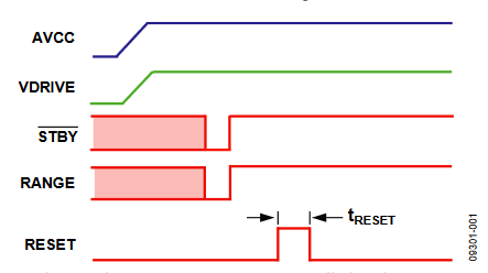
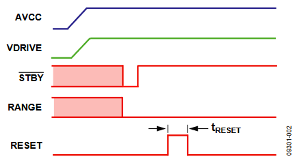
To place the AD7606/AD7607 into full shutdown mode, the STBY and RANGE pins should be set low after the AVCC and VDRIVE supplies are established (see Figure 1 and Figure 2). When the STBY and RANGE pins are both low after power-up, or brought low after power-up, the AD7606/AD7607 are in full shutdown mode.

Figure 1. Placing the AD7606/AD7607 into Full Shutdown (±10 V Range).

Figure 2. Placing the AD7606/AD7607 into Full Shutdown (±5 V Range).
To place the AD7606/AD7607 into normal mode, for the ±10 V range, the STBY and RANGE pins are brought high (Figure 1).
For the ±5 V range, the STBY pin alone is brought high (see Figure 2). At this point, the REGCAPA, REGCAPB, and REGCAP pins power up to their correct potential as outlined in the AD7606and AD7607 data sheets. If a STBY pulse is used to power up the AD7606/AD7607, the duration of the pulse should be 500 ns minimum.
Once fully powered up, the AD7606/AD7607 should see a RESET rising edge to configure the AD7606/AD7607 for normal operation. The time between coming out of full shutdown and the RESET high edge is specified as tWAKE-UP SHUTDOWN,as outlined in the AD7606 and AD7607 data sheets.
Figure 1 shows how to control the STBY and RANGE pins for the ±10 V range. The STBY and RANGE pins return high to take the AD7606/AD7607 out of full shutdown mode and into normal mode and configure the AD7606/AD7607 for the ±10 V range. In Figure 2, the STBY pin alone is used to take the AD7606/AD7607 out of full shutdown mode. The RANGE pin can remain low to select the ±5 V range.
Conclusion
Implementing the above scheme after the AVCC and VDRIVE supplies are established makes the AD7606/AD7607 immune to slow supply ramp conditions and to delays between the AVCC and VDRIVE supply ramps.

