ADALM2000 Activity: Polyphase Filter Circuits

Objective

The objective of this lab activity is to examine polyphase filter circuits as a quadrature generation technique and to extend the differential tuned amplifier to create a polyphase amplifier or filter that can produce all four quadrature (90° increments) phases of an input signal source.

Background

The use of quadrature frequency conversion is common in modern wireless transceiver architectures because both amplitude modulation and phase modulation are deployed in today’s digital communication systems.

Figure 1 shows a simplified first-order polyphase circuit, as implemented in many quadrature demodulators, such as the ADL5380. This simple polyphase circuit consists of complementary RC subcircuits. A low-pass transfer function from the input to one output shifts the phase by –45° at the corner frequency, and a highpass transfer function to the other output shifts the phase by +45° at the corner frequency. The net phase difference between the two outputs will be 90°. If the R and C values of the two paths are matched, then both paths have the same corner frequency and, more importantly, the phase of one output tracks the other with a 90° phase shift for all frequencies. The relative amplitudes of the two output signals (LO I 0° and LO Q 90°) will only be equal at the –3 dB corner frequency of the two RC paths.

Figure 1. Simplified first-order polyphase filter.

The generation of quadrature local oscillator (LO) signals is an important functional block in sideband rejection heterodyne receivers. Quadrature accuracy, which is the phase accuracy of the in phase and quadrature 90° phase-shifted signals, directly determines the image reject ratio (IRR), an important specification determining the sensitivity of a receiver.

Materials

  • ADALM2000 Active Learning Module
  • Solderless breadboard and jumper wire kit
  • Two 1 nF capacitors (marked 102)
  • Two 1 kΩ resistors

Directions

Build the polyphase filter circuit shown in Figure 2 on your solderless breadboard.

Figure 2. Polyphase filter circuit.

Hardware Setup

The blue squares in Figure 2 indicate where to connect the ADALM2000 module AWG and scope channels. See Figure 3 for the breadboard circuit.

Figure 3. Simplified first-order polyphase filter breadboard connection.

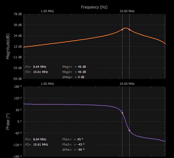
Open the Network Analyzer software tool in Scopy. Configure the frequency sweep to start at 10 kHz and stop at 30 MHz. Set the amplitude to 2 V and the offset to zero. Check the box Use Channel 1 as reference under the scope channel dropdown menu to measure the phase of one output path with respect to the other. See Figure 4.

Figure 4. Scopy Network Analyzer output.

Procedure

Calculate the expected RC corner frequency based on the R and C values you used. Run a single sweep of the frequency and be sure to save your data to a .csv file for later use in either MATLAB® or Excel.

Differential Polyphase Tuned Amplifier

By adding second-order L-C and C-L low- and high-pass filter sections as differential output loads in an NPN differential amplifier, we can generate all four 90° phases (0°, 90°, 180°, and 270°) of an input sine wave signal. Such a tuned amplifier is shown in Figure 5.

Figure 5. A polyphase amplifier.

Materials

  • ADALM2000 Active Learning Module
  • Solderless breadboard, and jumper wire kit
  • One SSM2212 NPN matched transistor pair (Q1, Q2)
  • Two 2N3904 NPN transistors (Q3, Q4)
  • Two 100 μH inductors (various other value inductors)
  • Two 1 nF capacitors (marked 102)
  • Two 0.1 μF capacitors (marked 104)
  • Two 10 Ω resistors
  • Two 150 Ω resistors
  • Two 470 Ω resistors
  • Three 1 kΩ resistors
  • One 10 kΩ resistor
  • Other resistors and capacitors as needed

Directions

Build the circuit shown in Figure 5 on your solderless breadboard. Use the SSM2212 matched transistor pair for Q1 and Q2. Transistors Q3 and Q4 can be 2N3904 devices. Set L1 = L2 = 100 μH and C1 = C2 = 1 nF. R1 should be equal to R2 and use 470 Ω for their values. Likewise, R3 should be equal to R4 and use 150 Ω for their values.

Hardware Setup

The blue squares in Figure 5 indicate where to connect the ADALM2000 module AWG, scope channels, and power supplies. Be sure to turn on the power supplies only after you double check your wiring. See Figure 6 for the breadboard circuit.

Figure 6. Polyphase amplifier breadboard connection.

Open the voltage supply control window to turn on and off the fixed +5 V and –5 V power supplies. Open the Network Analyzer software tool in Scopy. Configure the frequency sweep to start at 100 Hz and stop at 30 MHz. Set the amplitude to 1 V and the offset to zero.

Procedure

Calculate the expected LC corner frequency based on the L and C values used.

Turn on the power supplies. Connect Scope Input Channel 2 through an AC coupling capacitor (C4 in Figure 5) alternately to each of the four possible outputs at the ends of resistors R1, R2, R3, and R4. Run a single frequency sweep and store each sweep in a waveform snapshot to compare each output’s relative gain and phase response. Be sure to export all the frequency sweep data to a .csv file for further analysis in either Excel or MATLAB.

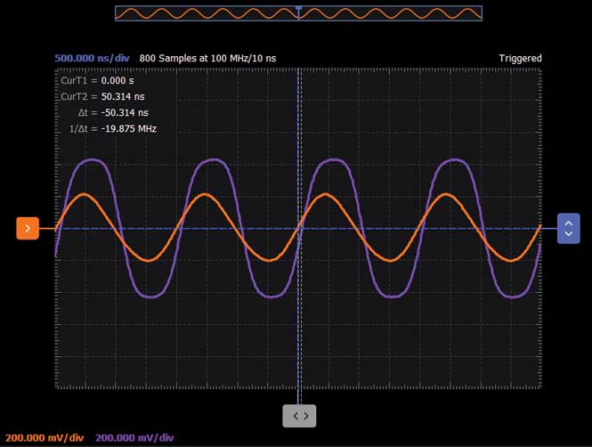
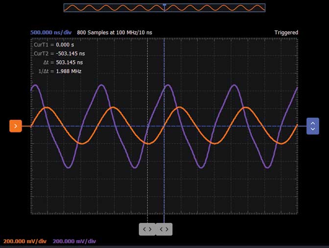
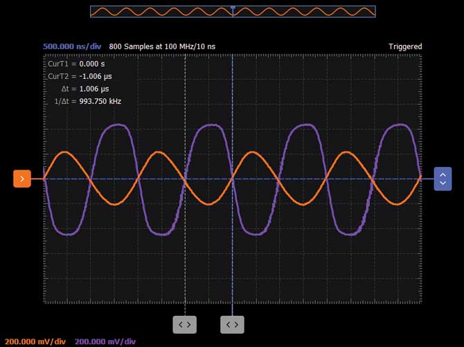
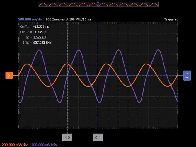
Using the scope and function generator software instruments (in the time domain), set the AWG frequency to the resonate frequency with the amplitude set to 1 V peak-to-peak. Trigger on Scope Channel 1. Observe the relative amplitudes and phases of the four outputs and store each waveform on Channel 2 as a reference channel to compare the amplitude and phase of each output. See figures 7 to 10.

Figure 7. 0° phase shift.
Figure 8. 90° phase shift.
Figure 9. 180° phase shift.
Figure 10. 270° phase shift.

Question

Can you briefly describe some practical applications of the polyphase filters?

You can find the answer at the StudentZone blog.

作者

Antoniu Miclaus

Antoniu Miclaus

Antoniu Miclaus现为ADI公司的系统应用工程师,从事ADI教学项目工作,同时为Circuits from the Lab®、QA自动化和流程管理开发嵌入式软件。他于2017年2月在罗马尼亚克卢日-纳波卡加盟ADI公司。他目前是贝碧思鲍耶大学软件工程硕士项目的理学硕士生,拥有克卢日-纳波卡科技大学电子与电信工程学士学位。

Doug Mercer

Doug Mercer

Doug Mercer 在1977至2009年间一直在ADI公司从事全职工作,最后14年担任ADI公司研究员。ADI公司高速转换器产品系列的30多款标准产品都有他的贡献,AD783就是其中一款。自2009年起,他转而担任ADI公司的兼职顾问研究员,最近主要是作为ADI公司与伦斯勒理工学院的联络人,从事本科生电气工程教育推广和发展方面的工作。