Lithium-Ion (Li-Ion) batteries are gaining popularity for portable systems due to their increased capacity at the same size and weight as the older NiCad and NiMH chemistries. For example,a portable computer equipped with a Li-Ion battery can have a longer operating time than a similar computer equipped with a NiMH battery. However, designing a system for Li-Ion batteries requires special attention to the charging circuitry to ensure fast, safe, and complete charging of the battery.
A new battery-charging IC, the ADP3810, is designed specifically for controlling the charge of 1-to-4-cell Li-Ion batteries. Four high-precision fixed final battery-voltage options (4.2 V, 8.4 V, 12.6 V, and 16.8 V) are available; they guarantee the ±1% final battery voltage specification that is so important in charging Li-Ion batteries. A companion device, the ADP3811, is similar to the ADP3810, but its final battery voltage is user-programmable to accommodate other battery types. Both ICs accurately control the charging current to realize fast charging at currents of 1 ampere or more. In addition, they both have a precision 2.0-V reference, and a direct opto-coupler drive output for isolated applications.
Li-Ion Charging: Li-Ion batteries commonly require a constant current, constant voltage (CCCV) type of charging algorithm. In other words, a Li-Ion battery should be charged at a set current level (typically from 1 to 1.5 amperes) until it reaches its final voltage. At this point, the charger circuitry should switch over to constant voltage mode, and provide the current necessary to hold the battery at this final voltage (typically 4.2 V per cell).Thus, the charger must be capable of providing stable control loops for maintaining either current or voltage at a constant value,depending on the state of the battery.
The main challenge in charging a Li-Ion battery is to realize the battery's full capacity without overcharging it, which could result in catastrophic failure. There is little room for error, only ±1%. Overcharging by more than +1% could result in battery failure, but undercharging by more than 1% results in reduced capacity. For example, undercharging a Li-Ion battery by only 100 mV (-2.4% for a 4.2-V Li-Ion cell) results in about a 10% loss in capacity. Since the room for error is so small, high accuracy is required of the charging-control circuitry.To achieve this accuracy, the controller must have a precision voltage reference, a low-offset high-gain feedback amplifier,and an accurately matched resistance divider.The combined errors of all these components must result in an overall error less than ±1%.The ADP3810, combining these elements, guarantees the overall accuracy of ±1%, making it an excellent choice for Li-Ion charging.
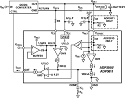
The ADP3810 and ADP3811: Figure 1 shows the functional diagram for the ADP3810/3811 in a simplified CCCV charger circuit. Two "gm" amplifiers (voltage input, current output) are key to the IC's performance. GM1 senses and controls the charge current via shunt resistance, RCS, and GM2 senses and controls the final battery voltage.Their outputs are connected in an analog "OR" configuration, and both are designed such that their outputs can only pull up the common COMP node.Thus,either the current amplifier or the voltage amplifier is in control of the charging loop at any given time.The COMP node is buffered by a "gm" output stage (GM3), the output current of which directly drives the dc-dc converter control input (via an opto-coupler in isolated applications).

The ADP3810 includes precision thin-film resistors to divide down the battery voltage accurately and compare it to an internal 2.0-V reference. The ADP3811 does not include these resistors, so the designer can program any final battery voltage with an external resistor pair according to the formula below. A buffer amplifier provides a high-impedance input to program the charge current using the VCTRL input, and an under voltage lock-out (UVLO) circuit ensures a smooth start-up.

To understand the "OR" configuration, assume that a fully discharged battery is inserted in the charger. The voltage of the battery is well below the final charge voltage, so the VSENSE input of GM2 (connected to the battery) brings the positive input of GM2 well below the internal 2.0-V reference. In this case, GM2 wants to pull the COMP node low, but it can only pull up, so it has no effect at the COMP node. Since the battery is dead, the charger starts to increase the charge current and the current loop takes control.The charge current develops a negative voltage across the 0.25-ohms current-shunt resistor (RCS). This voltage is sensed by GM1 through the 20-kohms resistor (R3). At equilibrium, (ICHARGERCS)/R3 = -VCTRL/80 kohms. Thus the charge current is maintained at

If the charge current tends to exceed the programmed level, the VCS input of GM1 is forced negative, which drives the output of GM1 high.This in turn pulls up the COMP node, increasing the current from the output stage, reducing the drive of the dc/dc converter block (which could be implemented with various topologies such as a flyback, buck, or linear stage), and finally, reducing the charge current.This negative feedback completes the charge current control loop.
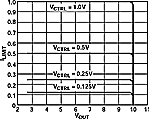
As the battery approaches its final voltage, the inputs of GM2 come into balance. Now GM2 pulls the COMP node high and the output current increases, causing the charge current to decrease, maintaining VSENSE and VREF equal. Control of the charging loop has changed from GM1 to GM2. Because the gain of the two amplifiers is very high, the transition region from current to voltage control is very sharp, as Figure 2 shows.This data was measured on a 10-V version of the off-line charger of Figure 3.

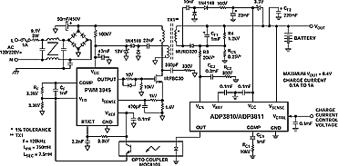
Complete Off-Line Li-Ion Charger: Figure 3 shows a complete charging system using the ADP3810/3811. This off-line charger uses the classic flyback architecture to create a compact, low cost design. The three main sections of this circuit are the primary-side controller, the power FET and flyback transformer, and the secondary-side controller.This design uses an ADP3810, directly connected to the battery, to charge a 2-cell Li-Ion battery to 8.4 V at a programmable charge current from 0.1 to 1 A.The input range is from 70 to 220 V ac-for universal operation.The primary side pulsewidth modulator used here is the industry-standard 3845, but other PWM components could be used. The actual output specifications of the charger are controlled by theADP3810/3811, which guarantees the final voltage within ±1%.

The current drive of the ADP3810/3811's control output directly connects to the photo-diode of an opto-coupler with no additional circuitry. Its 4-mA output current capability can drive a variety of opto-couplers-an MOC8103 is used here. The current of the photo-transistor flows through RF, setting the voltage at the 3845's COMP pin and thus controlling the PWM duty cycle. The controlled switching regulator is designed so that increased LED current from the opto-coupler reduces the duty cycle of the converter.
While the signal from the ADP3810/3811 controls the average charge current, the primary side should have a cycle by cycle limit of the switching current. This current limit has to be designed such that, with a failed or malfunctioning secondary circuit or opto-coupler, or during start up, the primary power circuit components (the FET and transformer) won't be over-stressed. When the secondary side VCC rises above 2.7 V, the ADP3810/ 3811 takes over and controls the average current. The primary side current limit is set by the 1.6-ohms current sense resistor connected between the power NMOS transistor, IRFBC30, and ground.
The ADP3810/3811, the core of the secondary side, sets the overall accuracy of the charger. Only a single diode is needed for rectification (MURD320) and no filter inductor is required.The diode also prevents the battery from back driving the charger when input power is disconnected.A 1000-µF capacitor (CF1) maintains stability when no battery is present. RCS senses the average current (see above), and the ADP3810 is connected directly (orADP3811 through a divider) to the battery to sense and control its voltage.
With this circuit, a complete off-line Li-Ion battery charger is realized.The flyback topology combines anAC/DC converter with the charger circuitry to give a compact, low-cost design. The accuracy of this system depends on the secondary side controller, the ADP3810/3811. The device's architecture also works well in other battery charging circuits. For example,a standard dc-dc buck type of charger can easily be designed by pairing the an ADP3810 and an ADP1148. A simple linear charger can also be designed with just the ADP3810 and an external pass transistor. In all cases, the inherent accuracy of the ADP3810 controls the charger and guarantees the ±1% final battery voltage needed for Li-Ion charging.

