Originally intended to carry LAN traffic, category-5 (Cat-5) unshielded twisted-pair (UTP) cable has become an economical solution in many other signal-transmission applications, owing to its respectable performance and low cost. For instance, an application that has become popular is keyboard-video-mouse (KVM) networking, in which three of the four twisted pairs carry the red, green, and blue (RGB) video signals.
Like any transmission medium, Cat-5 imposes transmission losses on the signals it carries, manifested as signal dispersion and loss of high-frequency content. Unless something is done to compensate for these losses, they can render the cables useless for transmitting high-resolution video signals over reasonable distances. Presented here is a practical technique to compensate for Cat-5 losses by introducing an equalizer (EQ), with eleven (11) switchable cable-range settings, at the receiving end of the cable. Because each setting of the EQ provides the proper amount of frequency-dependent gain to make up for the cable losses, the EQ-cable combination becomes suitable for high-resolution video transmission.
The first step in the EQ design is to derive a model for the Cat-5 frequency response. It is well known that the frequency response of metallic cable follows a low-pass characteristic, with an exponential roll-off that depends on the square root of frequency. Figure 1 depicts this relationship for lengths of Cat-5 from 100 feet (30.48 m) through 1000 feet (304.8 m), in 100-foot increments. In this illustration, it should be evident that the power loss at a given frequency is characterized by a constant attenuation rate (expressed in dB/ft).
Table I presents the Cat-5 equivalent voltage-attenuation magnitudes as a function of frequency for the same cable lengths as shown in Figure 1.
| Frequency | 100 ft | 200 ft | 300 ft | 400 ft | 500 ft | 600 ft | 700 ft | 800 ft | 900 ft | 1000 ft |
| 1 MHz | 0.932 | 0.869 | 0.8100 | 0.7550 | 0.7040 | 0.65600 | 0.6120 | 0.57000 | 0.53200 | 0.496000 |
| 14 MHz | 0.866 | 0.750 | 0.6490 | 0.5620 | 0.4870 | 0.42200 | 0.3650 | 0.31600 | 0.27400 | 0.237000 |
| 10 MHz | 0.796 | 0.634 | 0.5040 | 0.4020 | 0.3200 | 0.25400 | 0.2030 | 0.16100 | 0.12800 | 0.102000 |
| 16 MHz | 0.750 | 0.562 | 0.4220 | 0.3160 | 0.2370 | 0.17800 | 0.1330 | 0.10000 | 0.07500 | 0.056300 |
| 20 MHz | 0.722 | 0.521 | 0.3760 | 0.2710 | 0.1960 | 0.14100 | 0.1020 | 0.07350 | 0.05300 | 0.038300 |
| 31 MHz | 0.663 | 0.440 | 0.2920 | 0.1940 | 0.1280 | 0.08510 | 0.0565 | 0.03750 | 0.02480 | 0.016500 |
| 63 MHz | 0.551 | 0.303 | 0.1670 | 0.0920 | 0.0507 | 0.02790 | 0.0154 | 0.00846 | 0.00466 | 0.002570 |
| 100 MHz | 0.462 | 0.214 | 0.0987 | 0.0456 | 0.0211 | 0.00973 | 0.0045 | 0.00208 | 0.00096 |
0.000444 |
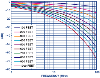
Using the data in Table I, the frequency response for each cable length can be approximated by a mathematical model based on a negative-real-axis pole-zero transfer function. Any one of the many available math software packages with the capability of least-squares polynomial curve fitting can be used to perform the approximation. Figure 1 suggests that, for long cables at high frequencies—because of the steepening slope, exceeding 20 dB/decade—consecutive negative-real-axis poles are required to obtain a close fit, while at low frequencies—to fit the nearly linear slope—alternating poles and zeros are required. As an extreme example, the frequency response for 1000 feet of cable at 100 MHz is rolling off approximately as 1/f4, which can only be attained by a model having multiple consecutive poles.
Equalization is achieved by passing the signal received over the cable through an equalizer whose transfer function is the reciprocal of the cable pole-zero model’s transfer function. To neutralize the cable’s frequency-dependency, the EQ has poles that are coincident with the zeros of the cable model and zeros that are coincident with the poles of the cable model.
One of the properties of passive RC networks is that the alternating poles and zeros of their driving-point impedances are restricted to the negative real axis. This property also holds for those operational-amplifier circuits having a transfer function determined by the simple ratio of feedback-impedance to gain-impedance (Zf/Zg), where these impedances are RC networks. (The property does not hold for other cases, such as active RC filter sections that synthesize conjugate pole-pairs.)
For a practical equalizer design, we prefer that an EQ be based on a single amplifier stage in order to keep its adjustability manageable and to minimize cost and complexity. The equalizer to be discussed here uses RC networks of the former type, described by Budak, with alternating poles and zeros; but such a design precludes the use of a single amplifier stage to realize the consecutive zeros required to compensate for consecutive poles in the cable model at all frequencies. As a compromise that will provide good equalization for all but long cables at high frequencies, the design chosen uses a single amplifier to realize two zeros and two poles, alternating on the negative real axis.
Because equalization requires increased gain at the high end of the band, a low-noise amplifier is required. To avoid introducing significant errors due to amplifier dynamics, a large gain-bandwidth product is needed. For the specific design requirements of this application, the amplifier must have the capacity to perform frequency-dependent differential-to-single-ended transformations with voltage gain. The Analog Devices AD8129, just such an amplifier, is the heart of the basic frequency-dependent gain stage in the EQ. Figure 2 shows the dual-differential-input architecture of the AD8129, and its standard closed-loop configuration for applications requiring voltage gain.
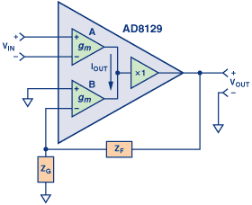
As can be seen, the AD8129 circuitry and operation differ from those of the traditional op amp; principally, it provides the designer with a beneficial separation of circuitry between the differential input and the feedback network. The two input stages are high-impedance, high-common-mode-rejection (CMR), wideband, high-gain transconductance amplifiers with closely matched gm. The output currents of the two transconductance amplifiers are summed (at high impedance), and the voltage at the summing node is buffered to provide a low impedance output. The output current of amplifier A equals the negative of the output current of amplifier B, and their transconductances are closely matched, so negative feedback applied around amplifier B drives vout to the level that forces the input voltage of amplifier B to equal the negative of the input voltage of amplifier A. From the above discussion, the closed-loop voltage gain for the ideal case can be expressed as:
 |
(1) |
The EQ is designed using this gain equation, with RC networks for Zf and Zg. Its canonical circuit is depicted in Figure 3, which represents an EQ designed to compensate for a given length of cable.
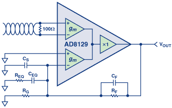
In Figure 3, the high differential input impedance of the upper transconductance amplifier facilitates provision of a good impedance match for the signal to be received over the Cat-5 cable; the lower amplifier provides the negative feedback circuit that implements the frequency-dependent gain. The Bode plot for the circuit has a high-pass characteristic, as shown in Figure 4. Zn and Pn are the respective zeros and poles of the equalizer.
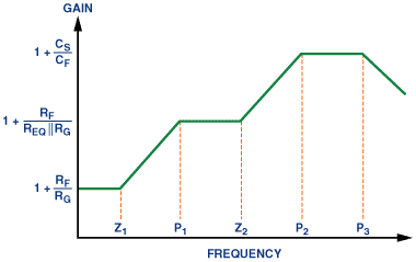
In the following analysis, where the pole-zero pairs in Figure 4 are sufficiently separated, the capacitors can be approximated as short- or open circuits. The pole- and zero frequencies are expressed in radians per second. At low frequencies, all capacitors are open circuits, and the gain is simply

This gain, set to compensate for flat (i.e., dc) losses, includes any loss due to matching and the cable’s low-frequency flat loss. It also provides the flat gain required to stabilize the AD8129 when equalizing short cables (to be covered in greater depth below).
Moving up in frequency, the lowest-frequency pole-zero EQ section, comprising the series-connected REQ and CEQ, starts to take effect, producing Z1 and P1. By approximating Cf and CS as open circuits, the following equations can be written:
 |
(2) |
 |
(3) |
The magnitude of the frequency response asymptotically approaches

as CEQ approaches a short circuit.
As frequency increases, CS begins to take effect, introducing another zero, Z2. The primary function of Cf is to keep the amplifier stable by compensating for CS. By initially approximating Cf as an open circuit (Cf <<CS), and presuming that Z2 is sufficiently far in frequency from P1 that CEQ can be considered as having negligible impedance compared to REQ, the approximate expression for Z2 can be written:
 |
(4) |
Finally, P2 can be expressed as:
 |
(5) |
Between P2 and P3, the magnitude of the frequency response asymptotically approaches the closed-loop gain produced by the capacitive divider formed by Cf and CS,

This is the closed-loop gain at frequencies leading up to P3, so P3, which is due to the amplifier’s dominant-pole roll-off, can be approximated as:
 |
(6) |
where AO is the amplifier’s dc open-loop gain, and ωp is the amplifier’s dominant pole. This result follows directly from standard op-amp gain-bandwidth analysis. P3 is imposed by the gain-bandwidth product of the amplifier, and sets the approximate upper frequency limit of the equalizer. Using the above results, along with the cable’s pole-zero model, an EQ can be designed for any practical length of cable that can be modeled by two alternating pole-zero pairs, provided that the amplifier has a sufficiently high gain-bandwidth product.
In order for the EQ to be useful over a wide range of cable lengths, it must be adjustable. A simple means of adding adjustability is to switch different RC networks between the feedback pin of the AD8129 and ground. This scheme is illustrated in Figure 5.
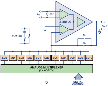
Each EQ section in Figure 5 is appropriate for a range of cable lengths. Section EQ0 covers 0 to 50 feet, and Section EQ10 covers 950 to 1000 feet. The other sections are centered on 100 feet, 200 feet, etc., and cover ±50 feet from their centers. This resolution is sufficient for most RGB applications.
Practical Matters
The AD8129 is stable for gains greater than 10 V/V, where it has a nominal phase margin of 56°, but if care is taken with regard to layout and parasitic capacitance, it can be successfully operated with a gain of 8, where it has approximately 45° of phase margin. This gain is required at high frequencies. For the longer cable lengths, sufficient high frequency gain is provided by the high-pass nature of the equalizer. For cable lengths between 0 and 300 feet, however, excess flat gain is required in order to keep the AD8129 stable. Because the excess gain is flat, it can be easily inserted by adjusting the Rf/Rg ratio, and removed by switching in the same amount of flat attenuation after the equalizer.
The AD8129’s input stage has a limited linear dynamic range (±0.5-V operating range). For optimum performance, it is best to attenuate the 700-mV RGB video signals by a factor of four before applying them to the AD8129 inputs. Sometimes the video signals are already attenuated by a factor of two before transmission over the cable. (This is not the matching loss—which is normally accounted for by using a cable driver with a gain of 2.) In this case, an additional factor-of-two attenuation can be inserted at the input to the AD8129 to produce an end-to-end flat attenuation factor of four. A buffer with a flat gain of four, placed after the EQ, is used to compensate for this attenuation (the AD8001 is an excellent choice for this stage). The buffer also simplifies the switched attenuator at the EQ output, which can be a simple L-pad.
The parasitic capacitance of each off channel in the ADG704 analog multiplexers used to select the EQ sections is 9 pF. The parasitic capacitance of the sum all of the unselected EQ sections is therefore quite large; it adds to the CS value of the selected EQ section. For the EQ sections from 400 to 1000 feet, this parasitic capacitance can usually be absorbed into CS. For the shorter sections, the excess closed-loop gain described above is used to compensate for the peaking caused by the parasitic capacitance. As a general rule, it is best to scale the impedances used in the EQ sections in such a way as to maximize the capacitance values, thus allowing absorption of as much parasitic capacitance into CS as possible. This can’t be carried too far however, since it reduces the associated resistances. The scaling is also limited by the parasitic inductance in the traces that connect the EQ sections. Small resistances provide little damping; if the resistance levels are too small, a moderate-Q tank circuit, resulting from the parasitic trace inductances and switch capacitances, can cause instability in the AD8129.
Optimizing the EQ PCB layout is of paramount importance. The major part of all power- and ground-plane copper must be removed from all layers under the traces that connect to the AD8129 summing node. Small ground-plane strips can be strategically placed as needed in these areas to provide low-Z return current paths, while minimizing stray capacitance at the summing node. The AD8129s and ADG704s should be in µSOIC packages, and the AD8001 should be in the SOT-5 package. Trace inductance in the EQ sections must be kept to an absolute minimum to avoid instability in the AD8129, so 0402 packages should be used for the resistors and capacitors, and the EQ sections should be laid out in such a way as to minimize trace lengths.
After the RC values that are based on the cable model have been determined, and the parasitic effects have been taken into account, a final tuning process in the time domain is required for RGB video applications. This is because one of the most important performance metrics for RGB video circuits is the step response; the step response of the cable and EQ combination must be tuned so as to exhibit fast rise time, minimum overshoot and ringing, and short settling time. CS has the greatest effect on overshoot and ringing, and the series connection of REQ and CEQ has the greatest effect on the long-term settling time. The positions of the pole and the zero produced by the series connection of REQ and CEQ can be altered somewhat without changing the frequency response a great deal, because they are placed where the cable’s frequency response has a rather gradual roll-off. This means that the equalized frequency response can appear to be quite good, while the positions of the pole and zero can be suboptimal from a step-response standpoint. It is therefore best to fine-tune the values of CS, REQ, and CEQ in the time domain by adjusting their values to produce a step response with the shortest settling time.
Since the equalizer must interface with long differential cables with no ground reference, the received signal may contain large common-mode voltage swings with respect to the power supply voltages at the receiver. It is therefore best to use dual power supplies of at least ±5 V. This also allows the output signal to swing to 0 V, which is generally required for video signals.
Conclusion
The equalizer presented here can stably compensate for lengths of Cat-5 cable from 0 to 1000 feet at frequencies to greater than 100 MHz at short cable lengths and to 25 MHz at 1000 feet, making it suitable for KVM networking and other high-resolution video transmission applications.
参考电路
Passive and Active Network Analysis and Synthesis, by Aram Budak, Houghton Mifflin, 1974.

