


Overview
Design Resources
Design & Integration File
- Schematic
- Bill of Materials
- Gerber Files
- PADS Files
- Assembly Drawing
Evaluation Hardware
Part Numbers with "Z" indicate RoHS Compliance. Boards checked are needed to evaluate this circuit.
- EVAL-SDP-CB1Z ($134.00) Eval Control Board SDP
Device Drivers
Software such as C code and/or FPGA code, used to communicate with component's digital interface.
AD719x GitHub no-OS Driver Source Code
ADT74x, ADT73x GitHub no-OS Driver Source Code
AD7192 IIO High Precision ADC GitHub Linux Driver Source Code
Features & Benefits
- Complete Analog front end for Process Control
- Inputs include RTD, thermocouple, 4-20 mA, +/- 10V
- Easily switch between the various input types
Product Categories
Markets and Technologies
Parts Used
Documentation & Resources
-
MT-101: Decoupling Techniques2/14/2015PDF954 kB
-
MT-023: ADC Architectures IV: Sigma-Delta ADC Advanced Concepts and Applications2/14/2015PDF936 kB
-
MT-022: ADC Architectures III: Sigma-Delta ADC Basics2/14/2015PDF289 kB
-
MT-031: Grounding Data Converters and Solving the Mystery of "AGND" and "DGND"3/20/2009PDF144 kB
-
MT-004: The Good, the Bad, and the Ugly Aspects of ADC Input Noise - Is No Noise Good Noise?3/4/2009PDF342 kB
Circuit Function & Benefits
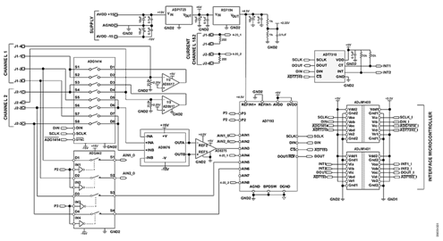
The circuit shown in Figure 1 provides a fully programmable universal analog front end (AFE) for process control applications. The following inputs are supported: 2-, 3-, and 4- wire RTD configurations, thermocouple inputs with cold junction compensation, unipolar and bipolar input voltages, and 4 mA-to-20 mA inputs.
Today, many analog input modules use wire links (jumpers) to configure the customer input requirements. This requires time, knowledge, and manual intervention to configure and reconfigure the input. This circuit provides a software controllable switch to configure the modes along with a constant current source to excite the RTD. The circuit is also reconfigurable to set common-mode voltages for the thermocouple configuration. A differential amplifier is used to condition the analog input voltage range to the Σ-Δ ADC. The circuit provides industry-leading performance and cost.
Because of the voltage gain provided by the AD8676 and AD8275, the design is particularly suitable for small signal inputs, all types of RTDs, or thermocouples.
The AD7193 is a 24-bit Σ-Δ ADC that can be configured to have four differential inputs or eight pseudo differential inputs. The ADuM1400 and ADuM1401 provide all the necessary signal isolation between the microcontroller and the ADC. The circuit also includes standard external protection and is compliant with the IEC 61000 specifications.


(Simplified Schematic: All Connections and Decoupling Not Shown)
Circuit Description
This circuit provides a fully programmable universal analog front end (AFE) for process control applications supporting 2-, 3-, and 4-wire RTD configurations, thermocouple inputs with cold junction compensation, unipolar and bipolar input voltages, and 4 mA-to-20 mA inputs as shown in the configuration diagram of Figure 2.
The ADG1414, a serially controlled octal SPST switch, is used to configure the selected measurement mode.


Voltage Measurement
This circuit supports the measurement of unipolar and bipolar signal ranges up to ±10 V. The input signal goes through a signal conditioning stage before conversion by the AD7193 ADC. The AD8676 amplifier buffers the inputs before the gain stage. The AD8275 is used to level shift the input signal and provides gain so that it matches the input range of the AD7193. The AD8275 output is biased with a common-mode voltage connected to its REF pin. This voltage is generated by the REF194 precision 4.5 V reference.
RTD Measurement
As shown in the connection table, this circuit supports 2-, 3-, and 4-wire RTD configurations. In this case, the transducer is a 1000 Ω platinum (Pt) RTD (resistive temperature device). The most accurate arrangement is a 4-lead RTD configuration. In the application shown, an external 200 μA current source provides the excitation current for the RTD, and the AD7193 is operated at gain of 16 to maximize the dynamic range in the circuit. The AD8617 amplifier is configured as a current source when the RTD measurement mode is selected. It is reconfigured in closed-loop to set the common-mode voltage when the thermocouple measurement is selected. The AD8617 is a dual low noise amplifier so that it can drive both input channels available on the board. The resistor configuring the current source must have a low temperature coefficient to avoid drift errors in the measurement circuit.
Thermocouple Measurement
In a thermocouple application, the voltage generated by the thermocouple is measured with respect to an absolute reference, provided externally to the ADC. The cold junction compensation is implemented using the ADT7310 16-bit temperature sensor. Because the signal from the thermocouple is small, and to maximize the dynamic range in the circuit, the AD7193 is operated at its highest gain range of 128. Because the input channel is buffered, large decoupling capacitors can be placed on the front end, if required, to eliminate any noise pickup that may be present in the thermocouple leads. The common-mode voltage for the thermocouple measurement is provided by the AD8617 amplifier.
4 mA-to-20 mA Current Measurement
This circuit also supports 4 mA-to-20 mA current measurement. The current is converted to a voltage using an on-board sense resistor. To use the full dynamic range of the ADC in the current measurement mode, a 200 Ω resistor is used. The sense resistor must have a low temperature coefficient to avoid temperature drift errors in the measurement circuit.
Regulator and Reference Selection
The ADP1720 was chosen as the 5 V regulator for this circuit.
The ADP1720 is a high voltage micropower linear regulator particularly suitable for industrial application. The 4.5 V REF194 was chosen as the reference for this circuit, and the E-grade device has an initial accuracy ±2 mV at 25°C and a drift of 5 ppm/°C maximum. It is a low dropout device and consumes less than 45 μA, with performance specifications over −40°C to +125°C.
Isolation
The ADuM1400 and the ADuM1401 are quad-channel digital isolators based on Analog Devices’ iCoupler® technology. These are used to provide isolation between the field side and the system microcontroller, with an isolation rating of 2.5 kV rms. Four wires are used through the ADuM1400, all for transmit (SCLK, DIN, ADG1414, ADT7310). Four wires are used through the ADuM1401: one for transmit (AD7193) and three for receive (INT1, INT2, DOUT). The DIN, DOUT, and SCLK lines are connected to the SPORT interface.
This design also includes external protection such as standard protection diodes and transient voltage suppressors (TVS devices) to enhance the robustness of the circuit. Refer to the schematics and other resources in the CN0209 Design Support Package: https://www.analog.com/CN0209-DesignSupport.
| Input Type | AD7193 Configuration | RMS Noise ($\text{nV}$) | Effective Resolution (Bits) |
| $\pm 10\text{ V}$ Input | Gain = 1; 50/60 Hz rejection; ODR = $50\text{ Hz}$ | $7940$ | $19.15$ |
| $4\text{ mA}$ to $20\text{ mA}$ | Gain = 1; 50/60 Hz rejection; ODR = $2.63\text{ Hz}$ | $931$ | $22.24$ |
| RTD | Gain = 16; 50/60 Hz rejection; ODR = $2.63\text{ Hz}$ | $243$ | $20.29$ |
| Thermocouple | Gain = 128; 50/60 Hz rejection; ODR = $2.63\text{ Hz}$ | $220$ | $19.23$ |
Figure 3 shows a histogram plot of the AD7193 output performance when configured in bipolar input mode with the inputs connected to ground. This histogram shows the effects of input-referred noise. The effective resolution achieved in this mode is 19.2 bits.


Circuit Evaluation & Test
This circuit uses the EVAL-CN0209-SDPZ circuit board and the EVAL-SDP-CB1Z System Demonstration Platform (SDP) evaluation board. The two boards have 120-pin mating connectors, allowing for the quick setup and evaluation of the circuit’s performance. The EVAL-CN0209-SDPZ board contains the circuit to be evaluated, as described in this note, and the SDP evaluation board is used with the CN0209 evaluation software to capture the data from the EVAL-CN0209-SDPZ circuit board.
Equipment Needed
- PC with a USB port and Windows® XP or Windows Vista® (32-bit) or Windows® 7 (32-bit)
- EVAL-CN0209-SDPZ Circuit Evaluation Board
- EVAL-SDP-CB1Z SDP Evaluation Board
- CN0209 Evaluation Software
- Power supply: +15 V and –15 V
- RTD temperature sensor
- Thermocouple
Getting Started
Load the evaluation software by placing the CN0209 Evaluation Software disc in the CD drive of the PC. Using "My Computer," locate the drive that contains the evaluation software disc and open the Readme file. Follow the instructions contained in the Readme file for installing and using the evaluation software.
Functional Block Diagram See Figure 1 of this circuit note for the circuit block diagram, and the file “EVAL-CN0209-SDPZ-SCH-Rev0.pdf” for the circuit schematics. This file is contained in the CN0209 Design Support Package: https://www.analog.com/CN0209-DesignSupport.
Setup
Connect the 120-pin connector on the EVAL-CN0209-SDPZ circuit board to the connector marked “CON A” on the EVAL-SDP-CB1Z evaluation (SDP) board. Nylon hardware should be used to firmly secure the two boards, using the holes provided at the ends of the 120-pin connectors. With power to the supply off, connect a +15 V power supply to the pin marked “+15 V,” a −15V power supply to the pin marked “−15 V” and “GND” on the board. Connect the USB cable supplied with the SDP board to the USB port on the PC. Note: Do not connect the USB cable to the mini USB connector on the SDP board at this time.
Test
Apply power to the ±15 V supply connected to the EVAL-CN0209-SDPZ circuit board. Launch the evaluation software and connect the USB cable from the PC to the USB mini-connector on the SDP board.
Once USB communications are established, the SDP board can now be used to send, receive, and capture serial data from the EVAL-CN0209-SDPZ board.
Voltage Measurement
If you want to measure the noise of the voltage measurement circuit, connect both inputs J3 and J4 to the ground. Then, click on the button of the matching channel of the software: either V1 (if you are using channel 1) or V2 (if you are using channel 2).
If you want to measure a voltage, connect both inputs J3 and J4 as shown in Figure 2, the analog input configuration table. Then, click on the matching button of the software as previously explained.
Results are displayed as a waveform and a histogram. You have the option to select the scale of the voltage result between μV, mV, and V using the switching button.
RTD Measurement
If you want to measure the temperature through an RTD temperature sensor, connect inputs J1, J2, J3, and J4 as shown in Figure 2. There are three different configurations of connection as you are using RTD 2-, 3-, or 4-wire. Then, click on the matching button of the software (RTD1 for channel 1, RTD2 for channel 2).
The switching button above the waveform allows you to display the result in Fahrenheit, Celsius, or Kelvin.
Thermocouple Measurement
If you want to measure the temperature through a thermocouple, connect inputs J1, J2, J3, and J4 as shown in Figure 2. Select the type of thermocouple you are using (B, E, J, K, R, S, T, N). Then, click on the TC button of the software (TC1 for channel 1, TC 2 for channel 2).
The switching button above the waveform allows you to display the result in Fahrenheit, Celsius, or Kelvin.
Current Measurement
If you want to measure a current, connect both inputs J5 and J6, as shown in Figure 2. Then, click on the matching button (I1 for channel 1, I2 for channel 2).
You can select the scale of the current result between μA, mA, and A using the switching button. Information regarding the SDP board can be found in the SDP User Guide.