
Intelligent Motion Control Solutions
Intelligent motion control combines precision feedback, advanced sensing, high performance control, and seamless connectivity to deliver deterministic motion solutions that enable highly flexible and efficient manufacturing. Motion control solutions in robotics have evolved from basic on/off fixed speed motors to complex multi-axis servo-drive solutions. This transformation has been driven by the increasing complexity of automation required to deliver higher levels of performance and autonomy in smart manufacturing.
Explore Applications in Intelligent Motion Control Solutions
-
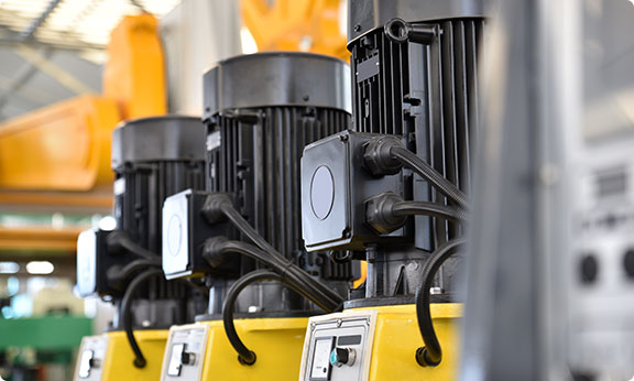
Motor Drive Solutions

-
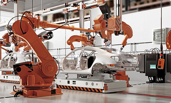
Position Encoder Systems


Accelerate Higher Value Motion Solutions with Access to System Insights
With a dedication to highest-level system performance, superior integration across technologies, and extensive industry expertise in all things motion control, we deliver complete solutions that enable precise motion control, accurate position and velocity tracking, and seamless real-time connectivity, with an increased focus on safety, robustness, reliability, and higher efficiency solutions. Our advanced machine health monitoring solutions and platforms can help manufacturers reduce system downtime and maintenance costs.


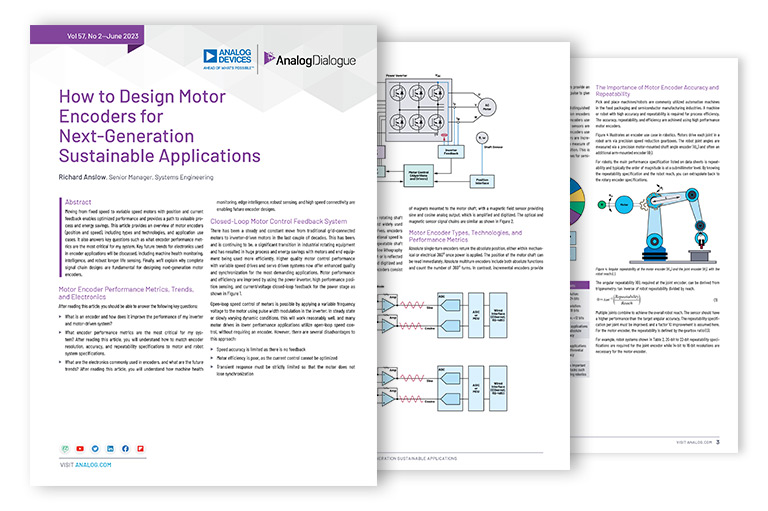


Featured Technical Articles
{{modalTitle}}
{{modalDescription}}
{{dropdownTitle}}
- {{defaultSelectedText}} {{#each projectNames}}
- {{name}} {{/each}} {{#if newProjectText}}
-
 {{newProjectText}}
{{/if}}
{{newProjectText}}
{{/if}}
{{newProjectTitle}}
{{projectNameErrorText}}