要約
This application note covers both the hardware and software aspects of developing serial applications on MxTNI™. There are special methods that must be used under certain circumstances. This application note discusses each of these and how they relate to both the internal and external serial ports. Also included is a discussion on the hardware required to utilize the external serial ports.
Introduction
Many devices use a serial port as a means for communicating with other electronic devices—everything from very well-known examples like personal computers and modems to manufacturing and industrial automation equipment. In fact, for many, a serial port provides the sole mechanism of communicating with the outside world. Such devices have no direct means of participating in a larger computer network. For this reason bridging the communications gap between serial-only devices to networked hosts is one of the most popular applications of Maxim Tiny Network Interface (MxTNI) technology. This application note covers both the hardware and software aspects of developing serial applications on MxTNI.
The MxTNI runtime environment for the MxTNI Board Model 390 (TBM390) can support up to four serial ports. Five serial ports are supported for the MxTNI Board Model 400 (TBM400). The serial ports are designated serial0 through serial4. The UARTs used by serial0, serial1, and serial4 are integrated within MxTNI's microcontroller, and are termed "internal" serial ports. The UARTs used by serial2 and serial3 require a dedicated external dual-UART chip. These are referred to as "external" serial ports.
Internal Serial Ports
Because serial0, serial1, and serial4 use internal UARTs, they are more efficient. The internal serial port drivers do not have to do nearly as much work to load or unload data from the UART. However, the internal serial ports are somewhat limited in terms of configuration options. The serial character configurations supported are:
- 8 data bits, 1 stop bit, no parity (default)
- 8 data bits, 1 stop bit, with parity (odd/even only)
- 7 data bits, 2 stop, no parity
- 7 data bits, 1 stop, with parity (odd/even only)
Configurations that use only 5 or 6 data bits or 1.5 stop bits are impossible if using the internal ports. However, this is seldom of practical concern. The options listed allow the internal ports to communicate with most common serial devices. The internal ports also support XON/XOFF flow control. However, a single set of hardware handshake lines is shared between all of the internal ports. This implies that only one port at a time can use RTS/CTS flow control. By default serial0 does not own the hardware handshake signals. Using TINIOS 1.0x, this ownership can be changed using the method setRTSCTSFlowControlEnable defined in class com.dalsemi.system.TINIOS. TINIOS 1.1x applications must use the setSerial method with TINIOS.SERIAL_SET_RTSCTS_FLOW_CONTROL as the first parameter.
public static boolean setRTSCTSFlowControlEnable(int portNumber, boolean enable)
	throws UnsupportedCommOperationException
public static int setSerial(int cmd, int port, boolean arr)
	throws UnsupportedCommOperationException
The port number must specify one of the internal serial ports (0, 1, or 4). If enable is true, the hardware handshake signals will be dedicated for use as hardware handshake signals for the specified serial port. If enable is false, the signals are free to be used with the com.dalsemi.system.BitPort class as general purpose TTL I/O.
There are a couple of additional points to keep in mind when using serial1. First, serial1 is by default dedicated to the task of communicating with the external 1-Wire® line driver. If your MxTNI hardware implementation does not require (or support) the use of the external 1-Wire adapter, serial1 can be reclaimed for use with a general-purpose serial port. To override serial1's default usage in TINIOS 1.0x, an application must invoke the enableSerialPort1 method defined in the com.dalsemi.system.TINIOS class. For TINIOS 1.1x, the setSerial method should be used, with TINOS.SERIAL_SET_ENABLE as the first parameter.
public static final void enableSerialPort1()
public static int setSerial(int cmd, int port, boolean arr)
	throws UnsupportedCommOperationException
This option persists across system boots. If you are using the TBM390, you will also need to disable the DS2480B 1-Wire driver. This is accomplished by grounding the EN2480 signal (pin 26 of the SIMM connector). The other thing to keep in mind, with respect to serial1, is that it does not support any data rates below 2400bps. This is generally not an issue when communicating with modern serial devices.
External Serial Ports
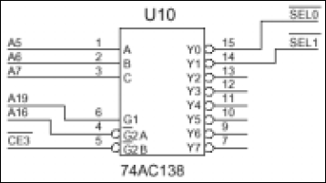
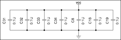
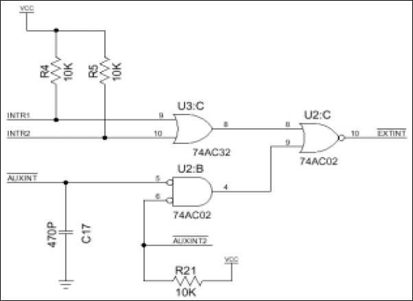
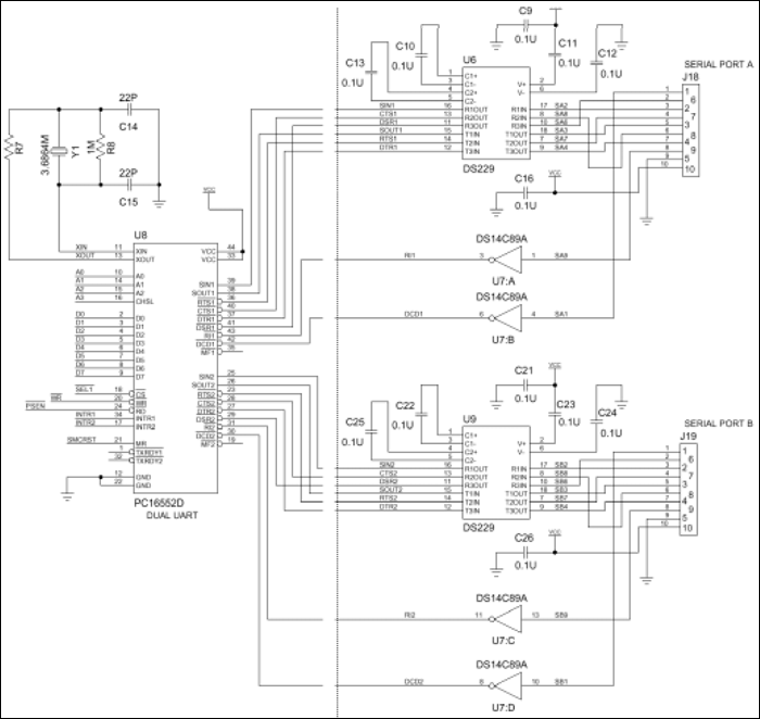
Before the external serial ports can be used, the necessary hardware must be added. The external serial ports consist of five modules: the DUART, the RS-232 level shifters, the interrupt circuit, the decode logic, and a group of decoupling capacitors. Some example circuits for each module that can be used with the E10 socket board are shown in the following figures. The list of materials used for these circuits is also included.

Figure 1. Decode circuitry.

Figure 2. Decoupling capacitors.

Figure 3. Interrupt circuitry.

Figure 4. DUART and RS-232 drivers.
| Component | Description | Package |
| C9–C13, C8, C16, C18, C19, C21–C25, C26, C31–C34 | 0.1µF | 1206 |
| C14 | 22pF | 1206 |
| C15 | 22pF | 1206 |
| C17 | 470pF | 1206 |
| J18, J19 | 10-pin, 0.1 center header connector | |
| R4, R5, R21 | 10kΩ | 1206 |
| R7 | 1.5kΩ | 1206 |
| R8 | 1MΩ | 1206 |
| U2 | 74AC02 | 14-pin SO |
| U3 | 74AC32 | 14-pin SO6 |
| U6, U9 | DS229 | 20-pin TSSOP |
| U7 | National | DS14C89A |
| U8 | National PC16552D | 44-PLCC |
| U10 | 74AC138 | 16-pin SO |
| Y1 | 3.6864MHz | HC49 |
Once the hardware has been added, the external serial ports must be enabled using the setExternalSerialPortEnable method (TINIOS 1.0x) or the setSerial method (TINIOS 1.1x) in the com.dalsemi.system.TINIOS class.
public static void setExternalSerialPortEnable(int portNum, boolean enable)
public static int setSerial(int cmd, int port, boolean arr)
	throws UnsupportedCommOperationException
The port number must specify one of the external ports (2 or 3). An enable value of true enables the use of external serial drivers. The settings established by setExternalSerialPortEnable persist across system boots.
The external serial drivers allow flexibility where the external UART hardware is mapped into MxTNI's memory space. The default base address for the external UART is 0x380020. This location can be overridden using the setExternalSerialPortAddress method (TINIOS 1.0x) or the setSerial method (TINIOS 1.1x) in com.dalsemi.system.TINIOS.
public static void setExternalSerialPortAddress(int portNum, int address)
public static int setSerial(int cmd, int port, boolean arr)
	throws UnsupportedCommOperationException
The port number must specify one of the external ports (2 or 3). The address refers to the base (or lowest) address consumed in the memory map. The settings established by setExternalSerialPortAddress persist across reboots.
Finally, where the internal serial ports are limited in their possible configurations, the external serial ports support all configurations that can be achieved using the Java™ Communications API with the exception of XON/XOFF flow control.
The MxTNI Runtime Environment, slush, and serial0
There are a few other things to keep in mind when developing applications that use serial communications. When MxTNI starts, it transmits progress messages on serial0 at the data rate of 115,200bps. This can cause confusion for certain embedded serial devices because the data is unsolicited and is transmitted at a speed that may be different from the speed for which the device is configured to receive data. TINIOS 1.0x applications can disable boot progress messages using the setSerialBootMessagesState method in class com.dalsemi.system.TINIOS. TINIOS 1.1x applications must use the setSerial method.
public static final void setSerialBootMessagesState(boolean on)
public static int setSerial(int cmd, int port, boolean arr)
	throws UnsupportedCommOperationException
The serial boot message state is persistent across system boots.
MxTNI's default shell, slush, also uses serial0 to transmit status messages and to allow user logins. To disable the serial server and prevent slush from chattering over serial0 during startup, the line "setenv SerialServer enable" should be removed from the .startup file. This will prevent slush from chattering over serial0. If you want the ability to use serial0 without disabling slush's serial server, you can use the setConsoleOutputEnabled method in the com.dalsemi.system.TINIOS class.
public static void setConsoleOutputEnabled(boolean set)
Calling this method with set equal to false instructs slush to boot silently so as not to interfere with any devices that may be connected to serial0.
The last thing to note is that no special action needs to be taken to force slush's serial server to release serial0 so another application can access it. Whenever another application requests serial0, slush will automatically relinquish its ownership. Just be sure to specify a sufficient timeout value when attempting to open the port (five seconds is generally large enough).
Conclusion
With the exception of the few methods mentioned here, all serial port programming on MxTNI can be done using the techniques defined in the Java Communications API. This provides developers an easy and standard way to build serial applications with MxTNI. These applications will allow MxTNI to interface with a variety of serial devices, including those devices that were never meant to be part of a larger network.


